
The filter should be inspected for external damage and/or leakage at least once a year. The fuel filter should be changed only as necessary. Toyota Motor Corporation recommends replacing the carbureted fuel filters at 15,000 miles and 30,000 miles on fuel injected models.
Fuel lines and connections, fuel tank vapor vent system hoses and fuel tank bands should be inspected every 60,000 miles or every 36 months. The fuel tank cap gasket should be replaced 60,000 miles or every 72 months.
REMOVAL & INSTALLATION Carbureted Engines
The fuel filter on carbureted engines is a plastic cylinder with two ports for the fuel. It is usually located in the engine compartment near the charcoal canister.
- Using a pair of pliers, expand the hose clamp on one side of the filter, and slide the clamp further down the hose, past the point to which the filter pipe extends. Remove the other clamp in the same manner.
- Grasp the hoses near the ends and twist them gently to pull them free from the filter pipe.
- Pull the filter from the clip and discard.
See Figures 1, 2 and 3
 |  |
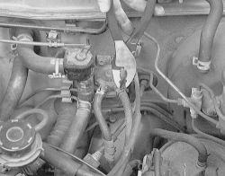
Fig. Fig. 1: Grasp the clamps and slide them up the hose slightly above the filter ends
| |
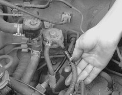
Fig. Fig. 2: Slide the hose off the end of the fuel filter end
| |
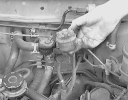
Fig. Fig. 3: Be carefull when removing the filter, some fuel may spill out if not held upright
- Install the new filter into the clip. The arrow must point towards the hose that runs to the carburetor.
- Push the hoses onto the filter pipes, then slide the clamps back into position.
- Start the engine and check for leaks.
See Figures 4, 5 and 6
The fuel filters on injected engines are a metal cylinder which is located in the engine compartment. You may find it under the injection manifold on some models. Each model varies.
- Unbolt the retaining screws and remove the protective shield from the fuel filter.
- Place a pan under the delivery pipe to catch the dripping fuel and SLOWLY loosen the union bolt to bleed off the fuel pressure. The fuel system is under pressure. Release pressure slowly and contain spillage. Observe "''no smoking/no open flame precautions''.
| |
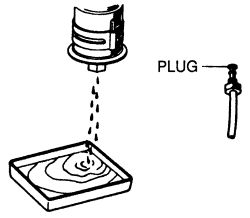
Fig. Fig. 4: Place a pan under the delivery pipe to catch the dripping fuel
- Remove the union bolt and drain the remaining fuel.
- Disconnect and plug the inlet line.
- Unbolt and remove the fuel filter.
When tightening the fuel line bolts to the fuel filter, you must use a torque wrench. The tightening torque is very important, as under or over tightening may cause fuel leakage. Insure that there is no fuel line interference and that there is sufficient space between the fuel lines and other components.
- Coat the flare unit, union nut and all bolt threads with engine oil.
- Hand-tighten the inlet line to the fuel filter.
| |
Fig. Fig. 5: Hand-tighten the fuel lines first
- Install the fuel filter and then tighten the inlet line nut to 22 ft. lbs. (29 Nm).
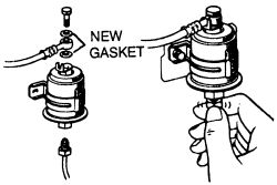
- Reconnect the delivery pipe using new gaskets and then tighten the union bolt to 22 ft. lbs. (29 Nm).
| |
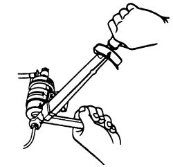
Fig. Fig. 6: A torque wrench is essential when tightening the fuel lines to the filter
- Run the engine for a short period and check for any fuel leaks.
- Install the protective shield.
See Figures 7 through 15
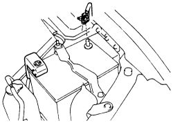
- Turn the ignition switch to the LOCK position. Disconnect the negative battery cable and wait at least 90 seconds before proceeding with working on the fuel system. This will depressureize the fuel system.
| |
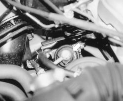
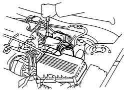
Fig. Fig. 7: The fuel filter can be hard to locate on these engines
| |
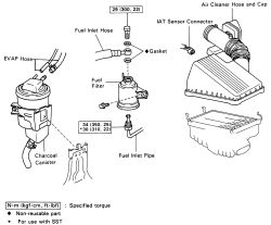
Fig. Fig. 8: Exploded view of the fuel filter mounting-1993-97 models
| |
Fig. Fig. 9: Disconnect the negative battery cable prior to all fuel system repairs
- Disconnect the Intake Air Temperature (IAT) sensor wiring.
- Loosen the air cleaner hose clamp bolt, the disconnect the four air cleaner cap clips.
| |
Fig. Fig. 10: Loosen the air cleaner hose clamp bolt
- Spearate the air cleaner hose from the throttle body, and remove the air cleaner cap together with the air cleaner hose.
- Disconnect the EVAP canister hose from the charcoal canister.
| |
Fig. Fig. 11: Remove both EVAP hoses from the charcoal canister
- Remove the charcoal canister from the bracket.
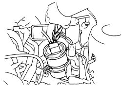
- Place a suitable container or shop towel under the fuel filter. Remove the union bolt and two gaskets, then slowly disconnect the fuel inlet hose from the fuel filter outlet.
| |
Fig. Fig. 12: Remove the union bolt and two gaskets from the fuel filter, then disconnect the inlet hose from the filter
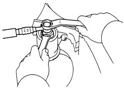
- Using a special wrench 09631-22020 or equivalent, disconnect the inlet pipe from the fuel filter. Remove the two bolts and the filter from the vehicle.
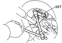
| |
Fig. Fig. 13: Using a special tool, disconnect the inlet pipe from the fuel filter
| |
Fig. Fig. 14: Remove the two filter mounting bolts, then separate the filter from the vehicle
- Install the fuel filter with the two bolts and tighten them to 43 inch lbs. (5 Nm).
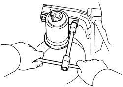
- Using the special wrench 09631-22020 or equivalent, connect the inlet pipe to the fuel filter. Tighten to 22 ft. lbs. (30 Nm). Using a torque wrench, tighten with a fulcrum length of 11.81 inch (30cm). Install the fuel inlet hose to the filter outlet using new gaskets and union bolt. Tighten to 22 ft. lbs. 30 Nm).

| |
Fig. Fig. 15: Install the filter inlet hose to the filter outlet, then tighten to 22 ft. lbs. (29 Nm)
- Install the charcoal canister to the bracket. Connect the two EVAP hoses to the canister.
- Connect the air cleaner hose to the throttle body. Install the air cleaner cap together with the air cleaner hose.
- Attach the IAT sensor wiring.
- Connect the negative battery cable. Start the engine and check for leaks. Reset any various digital equipment such as radio memory and the clock if necessary.