
TESTING
See Figure 1
 |  |
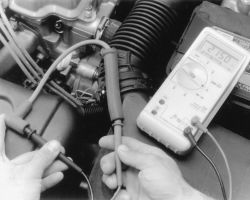
Fig. Fig. 1: Checking individual plug wire resistance with a digital ohmmeter
At every tune-up, visually inspect the spark plug cables for burns, cuts, or breaks in the insulation. Check the boots and the nipples on the distributor cap and coil. Replace any damaged wiring.
Every 30,000 miles or so, the resistance of the wires may be checked with an ohmmeter. Wires with excessive resistance will cause misfiring, and may make the engine difficult to start in damp weather. Generally the useful life of the cables is 30,000-50,000 miles.
To check resistance, remove the distributor cap, leaving the wires attached. Connect one lead of an ohmmeter to an electrode within the cap; connect the other lead to the corresponding spark plug terminal (remove it from the plug for this test). Replace any wire which shows a resistance over 25,000 ohms per wire.
It should be remembered that resistance is also a function of length; the longer the cable, the greater the resistance. Thus, if the cables on your car are longer than the factory originals, resistance will be higher, quite possibly outside these limits.
When installing new spark plug wires (cables), replace them ONE AT A TIME to avoid mix-ups. Start by replacing the longest one first. Install the boot firmly over the spark plug. Route the wire over the same path as the original. Insert the nipple firmly into the tower on the cap or the coil.
REMOVAL & INSTALLATION
See Figures 2, 3, 4, 5 and 6
- Disconnect the negative battery cable.
If there is no tape around to label the wires. It may be a good idea to remove one spark plug wire at a time so not to mix them up during installation.
- Label and disconnect the wires from each spark plug one at a time.
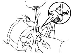
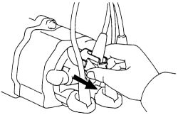
- Remove the spark plug wires from the distributor cap. On some models you may need to use a flat bladed tool to lift up the lock claw and disconnect the holder from the cap. Separate the wires at the grommet.
| |
Fig. Fig. 2: Lift up the lock claw and disconnect the holder from the distributor cap
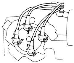
- Pull the plug wires from the retaining clamps.
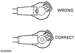
- Attach the holder and grommet portion to the distributor cap. Make sure that the holder is installed correctly to the grommet and cap.
| |
Fig. Fig. 3: Attach the holder and grommet portion to the distributor cap
- Check that the lock claw of the holder is engaged by lightly pulling on the holder.
| |
Fig. Fig. 4: Holder installation to the grommet and cap is important
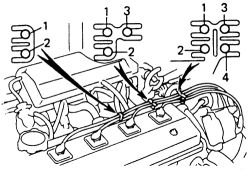
- Secure the wires with the clamps as shown.
| |
Fig. Fig. 5: Make sure the lock claw of the holder is engaged by lightly pulling the holder
| |
Fig. Fig. 6: Secure the plug wires with the clamps as shown