
GENERAL INFORMATION
Ignition timing is the measurement (in degrees) of crankshaft position at the instant the spark plug fires. Ignition timing is adjusted by loosening the distributor locking device and turning the distributor in the engine.
It takes a fraction of a second for the spark from the plug to completely ignite the mixture in the cylinder. Because of this, the spark plug must fire before the piston reaches TDC (top dead center, the highest point in its travel), if the mixture is to be completely ignited as the piston passes TDC. This measurement is given in degrees (of crankshaft rotation) before the piston reaches top dead center (BTDC). If the ignition timing setting for your engine is 10° BTDC, this means that the spark plug must fire at a time when the piston for that cylinder is 10° before top dead center of its compression stroke. However, this only holds true while your engine is at idle speed.
As you accelerate from idle, the speed of your engine (rpm) increases. The increase in rpm means that the pistons are now traveling up and down much faster. Because of this, the spark plugs will have to fire even sooner if the mixture is to be completely ignited as the piston passes TDC. To accomplish this, the distributor incorporates means to advance the timing of the spark as the engine speed increases.
On fuel injected vehicles there is no centrifugal advance or vacuum unit to advance the timing. All engine timing changes are controlled electronically by the ECU. This solid state "brain'' ECU receives data from many sensors and commands changes in spark timing based on immediate driving conditions. This instant response allows the engine to be kept at peak performance and economy throughout the driving cycle. Basic timing and idle speed can still be checked and adjusted on these engines.
If the ignition timing is set too far advanced (BTDC), the ignition and expansion of the air/fuel mixture in the cylinder will try to force the piston down while it is still traveling upward. This causes engine ping, a sound which resembles marbles being dropped into an empty tin can. If the ignition timing is too far retarded (after, or ATDC), the piston will have already started down on the power stroke when the air/fuel mixture ignites and expands. This will cause the piston to be forced down only a portion of its travel. This results in poor engine performance and lack of power.
Ignition timing adjustment is checked with a timing light. This instrument is connected to the number one (No. 1) spark plug of the engine. The timing light flashes every time an electrical current is sent from the distributor through the No. 1 spark plug wire to the spark plug. The crankshaft pulley and the front cover of the engine are marked with a timing pointer and a timing scale.
When the timing pointer is aligned with the 0 mark on the timing scale, the piston in the No. 1 cylinder is at TDC of it compression stroke. With the engine running, and the timing light aimed at the timing pointer and timing scale, the stroboscopic (periodic) flashes from the timing light will allow you to check the ignition timing setting of the engine. The timing light flashes every time the spark plug in the No. 1 cylinder of the engine fires. Since the flash from the timing light makes the crankshaft pulley seem to stand still for a moment, you will be able to read the exact position of the piston in the No. 1 cylinder on the timing scale on the front of the engine.
If you're buying a timing light, make sure the unit you select is rated for electronic or solid-state ignitions. Generally, these lights have two wires which connect to the battery with alligator clips and a third wire which connects to the No. 1 plug wire. The best lights have an inductive pick-up on the third wire; this allows you to simply clip the small box over the wire. Older lights may require the removal of the plug wire and the installation of an in-line adapter. Since the spark plugs in the twin-cam engines are in deep wells, rigging the adapter can be difficult. Buy quality the first time and the tool will give lasting results and ease of use.
INSPECTION & ADJUSTMENT Carbureted Engines
See Figures 1, 2, 3, 4 and 5
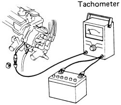
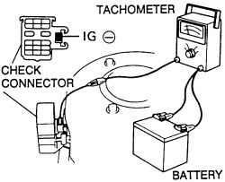
- Warm-up the engine, then turn the ignition OFF. Connect a tachometer to both battery terminals and to the service connector coming from the distributor.
 |  |
Fig. Fig. 1: Attach a tachometer to both the battery and terminals of the service connector coming from the distributor-1988-89 models
- Clean off the timing marks. The marks are on the crankshaft pulley and timing cover. The timing notches in the crankshaft pulley are normally marked at the factory with red or white paint. You may want to retouch them if they are dark, using chalk or paint. Fluorescent (dayglow) paint is excellent for this purpose. You might have to bump the engine around with the starter (just touch the key to the START position very briefly) to find the pulley marks.
- Connect a timing light according to the manufacturer's instructions.
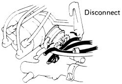
- Disconnect the vacuum line(s) from the distributor vacuum unit. Clamp or plug the line(s); golf tees are excellent for this job. Any vacuum leak will make the engine run poorly.
- Be sure that the all wires are clear of the fan and moving belts, pulleys etc. Start the engine.
- Allow the engine to run at idle speed with the gear shift in Neutral (manual) and Park (P) with automatic transmission. Use the tachometer to check idle speed and adjust the idle if necessary. Idle speed is 750 rpm with a manual transmission or 850 rpm with an automatic transmission.
| |
Fig. Fig. 2: Disconnect the vacuum line(s) from the distributor vacuum unit
| |
Fig. Fig. 3: With the engine idling, use a timing light to check the timing
- Point the timing light at the marks indicated in the chart and illustrations. With the engine at idle, timing should be at the specification given on the "Tune-Up Specifications'' chart.
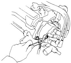
- If the timing is not at the specification, loosen the pinch bolt (hold-down bolt) at the base of the distributor just enough so that the distributor can be turned. Turn the distributor to advance or retard the timing as required. Once the proper marks are seen to align, timing is correct. Tighten the hold-down bolt.
| |
Fig. Fig. 4: If necessary, loosen the distributor bolts and turn the distributor, then recheck the timing
Remember that you are using metal tools on a running engine. Watch out for moving parts and don't touch any of the spark plug wires with the wrench.
| |
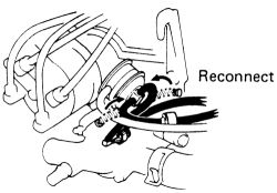
Fig. Fig. 5: Reconnect the vacuum line(s) to the distributor vacuum unit
- Recheck the timing. Stop the engine; disconnect the tachometer and timing light.
See Figures 6, 7, 8, 9, 10 and 11
This service procedure is for setting base ignition timing. Refer to underhood emission sticker for any additional service procedure steps and/or specifications.
These engines require a tachometer hook-up to the check connector-see illustrations. NEVER allow the tachometer terminal to become grounded; severe and expensive damage can occur to the coil and/or igniter.
Some tachometers are not compatible with this ignition system, confirm the compatibility of your unit before using.
- Warm the engine to normal operating temperature. Turn off all electrical accessories. Do not attempt to check timing specification or idle speed on a cold engine.
| |
Fig. Fig. 6: Attach the tachometer to the battery and check connector terminals
- Connect a tachometer (connect the tachometer (+) terminal to the terminal IG- of the check connector) and check the engine idle speed to be sure it is within the specification given in the Tune-Up Specifications chart or underhood emission sticker.
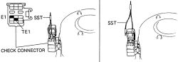
- Remove the cap on the diagnostic check connector. Using a small jumper wire or Special Service Tool SST 09843-18020, short terminals TE1 (test terminal No. 1) and E1 (earth-ground) together.
- If the timing marks are difficult to see, shut the engine OFF and use a dab of paint or chalk to make them more visible.
- Connect a timing light according to the manufacturer's instructions.
| |
Fig. Fig. 7: Early type of check connector and SST tool (jumper wire) for base timing adjustment
| |
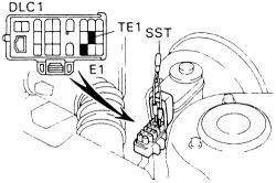
Fig. Fig. 8: Using the SST 09843-18020 or a jumper wire, connect terminals TE1 and E1 of the DLC1 (also used on OBD-II)
| |
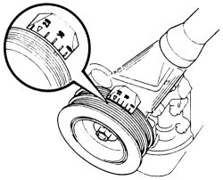
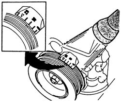
Fig. Fig. 9: Ignition timing marks 4A-GE engine-note the small notch on the pulley, this is the mark to align with the degree scale
| |
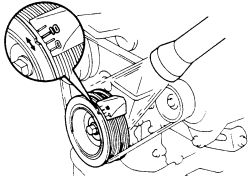
Fig. Fig. 10: Timing marks 4A-FE and 7A-FE engines
- Start the engine and use the timing light to observe the timing marks. With the jumper wire in the check connector the timing should be to specifications (refer to underhood emission sticker as necessary) with the engine fully warmed up (at correct idle speed) and the transmission in correct position. If the timing is not correct, loosen the bolts at the distributor just enough so that the distributor can be turned. Turn the distributor to advance or retard the timing as required. Once the proper marks are seen to align with the timing light, timing is correct.
| |
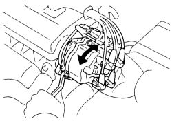
Fig. Fig. 11: If necessary, loosen the 2 mounting bolts and turn the distributor to adjust the timing
- Without changing the position of the distributor, tighten the distributor bolts and double check the timing with the light (check idle speed as necessary).
- Disconnect the jumper wire or Special Service Tool (SST) at the diagnostic check connector.
This jumper will be used repeatedly during diagnostics in later sections. Take the time to make a proper jumper with correct terminals or probes. It's a valuable special tool for very low cost.
- Refer to the underhood emission sticker for timing specification and any additional service procedure steps. If necessary, repeat the timing adjustment procedure.
- Shut the engine OFF and disconnect all test equipment. Roadtest the vehicle for proper operation.
See Figures 12 and 13
Toyota's hand-held tester or an equivalent OBD-II scan tool must be used for this procedure.
- Warm the engine to normal operating temperature.
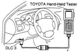
- Connect an OBD-II compliant scan tool to the DLC3 located under the dash on the driver's side. Refer to for more information.
| |
Fig. Fig. 12: Connect an OBD-II scan tool to the DLC3 located under the driver's side of the dash
- Connect the timing light to the engine.
- Using SST 09843-18020 or its equivalent jumper wire, connect terminals TE1 and E1 of the DLC1 under the hood.
- After the engine speed is kept at about 1000-1500 rpm for 5 seconds, check that it returns to idle speed.
- Check the ignition timing, the reading should be 10° BTDC at idle.
| |
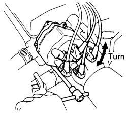
Fig. Fig. 13: Loosen the hold-down bolts and rotate the distributor to adjust
- On 4A-FE engines, if adjustment is necessary, loosen the 2 hold-down bolts, and adjust by turning the IIA. Tighten the hold-down bolts to 14 ft. lbs. (20 Nm), and recheck the ignition timing.
- Remove the jumper wire from the DLC1.
- Recheck the timing, the mark ranges from 5°-15° BTDC at idle.
- Disconnect the scan tool.
- Disconnect the timing light.