
GENERAL INFORMATION
Check and adjust the valve clearance every 60,000 miles or 72 months.
Valve clearance is one factor which determines how far the intake and exhaust valves will open into the cylinder. If the valve clearance is too large, part of the lift of the camshaft will be used up in removing the excessive clearance, thus the valves will not be opened far enough. This condition has two effects, the valve train components will emit a tapping noise as they take up the excessive clearance, and the engine will perform poorly, since the less the intake valve opens, the smaller the amount of air/fuel mixture that will be admitted to the cylinders. The less the exhaust valves open, the greater the back-pressure in the cylinder which prevents the proper air/fuel mixture from entering the cylinder.
If the valve clearance is too small, the intake and exhaust valves will not fully seat on the cylinder head when they close. When a valve seats on the cylinder head it does two things, it seals the combustion chamber so none of the gases in the cylinder can escape and it cools itself by transferring some of the heat it absorbed from the combustion process through the cylinder head and into the engine cooling system. Therefore, if the valve clearance is too small, the engine will run poorly due to gases escaping from the combustion chamber, and the valves will overheat and warp since they cannot transfer heat unless they are touching the seat in the cylinder head.
ADJUSTMENT 1988-92 Models
See Figures 1 through 8
The use of the correct special tools or their equivalent is REQUIRED for this procedure. The valve adjustment requires removal of the adjusting shims (Tool kit J-37141 available from Kent-Moore Tool or a Toyota equivalent No. 09248-55010) and accurate measurement of the shims with a micrometer. A selection of replacement shims (refer to parts department of your Toyota dealer) is also required. Do not attempt this procedure if you are not equipped with the proper tools. Valves on these engines are adjusted with the engine cold. Do not attempt adjustment if the engine has been run within the previous 4 hours. An overnight cooling period is recommended.
- Remove the spark plug wires from the valve cover.
- Remove the valve cover following procedures discussed in .
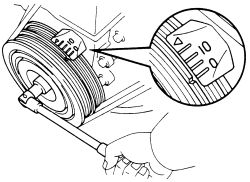
- Turn the crankshaft to align the groove in the crankshaft pulley with the 0 mark on the timing belt cover. Removing the spark plugs makes this easier, but is not required.
 |  |
Fig. Fig. 1: Turn the crankshaft pulley and align its groove with the timing mark 0
- Check that the lifters on No.1 cylinder are loose and those on No.4 are tight. If not, turn the crankshaft pulley one full revolution (360°).
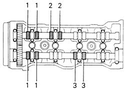
- Using the feeler gauge, measure the clearance on the valves in the positions shown in the diagram labeled First Pass. Make a written record of any measurements which are not within specification.
| |
Fig. Fig. 2: Check these valves in the first pass only
-
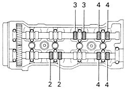
Rotate the crankshaft pulley one full turn (360°) and check the clearance on the other valves. The positions are shown on the diagram labeled Second Pass. Any measurements not within specification should be added to your written record.
Intake clearance COLD: 0.006-0.010 in. (0.15-0.25mm)Exhaust clearance COLD: 0.008-0.012 in. (0.20-0.30mm)Intake clearance HOT: 0.008-0.012 in. (0.20-0.30mm)Exhaust clearance HOT: 0.010-0.014 in. (0.26-0.36mm)
-
For ANY given valve needing adjustment:
- Turn the crankshaft pulley until the camshaft lobe points upward over the valve. This takes the tension off the valve and spring.
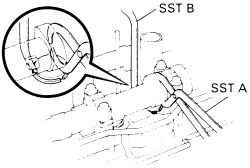
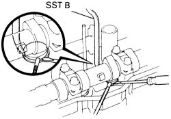
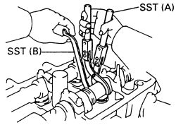
- Using the forked tool (SST-A), press the valve lifter downward and hold it there. Some tool kits require a second tool for holding the lifter in place (SST-B), allowing the first to be removed.
- Using small magnetic tools, remove the adjusting shim from the top of the lifter.
-
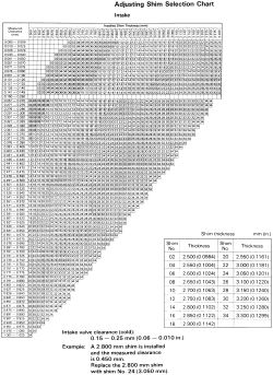
Use the micrometer and measure the thickness of the shim removed. Determine the thickness of the new shim using the formula below or the selection charts. For the purposes of the following formula, T = Thickness of the old shim; A = Valve clearance measured; N = Thickness of the new shim
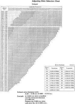
Intake side (camshaft nearest intake manifold): N = T + (A - 0.20mm (0.008 in.))Exhaust side (camshaft nearest exhaust manifold): N = T + (A - 0.25mm (0.010 in.)
| |
Fig. Fig. 3: Check these valves in the second pass only
| |
Fig. Fig. 4: Press down the valve lifter with SST-A and hold the lifter down with SST-B
| |
Fig. Fig. 5: Remove the adjusting shim with a flatbladded tool and a magnetic finger
| |
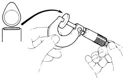
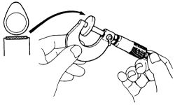
Fig. Fig. 6: Using a micrometer, measure the removed adjusting shim size
| |
Fig. Fig. 7: Shim selection chart-intake
| |
Fig. Fig. 8: Shim selection chart-exhaust
- Select a shim closest to the calculated thickness. Use the lifter depressor tool to press down the lifter and install the shim. Shims are available in 17 sizes from 0.0984-0.1299 in. (2.50mm-3.30mm). The standard increment is 0.0020 in. (0.05mm).
- Repeat steps a through e for each valve needing adjustment.
- Reinstall the valve cover, following the procedures outlined in .
- Install the spark plug wires.
- Check and adjust the timing and idle speed, following the procedures outlined in this section. Road test the vehicle for proper operation.
See Figures 9 through 23
Inspect and adjust the valve clearance while the engine is cold.
- Remove the spark plug wires from the valve cover.
- Remove the valve cover and gasket as described in .
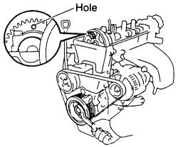
- Set the No. 1 cylinder to TDC by turning the crankshaft pulley and align its groove with the timing mark "0" of the No. 1 timing cover. Check that the hole of the camshaft timing pulley is aligned with the timing mark of the bearing cap. If not, turn the crankshaft one revolution (360°).
- To inspect the valve clearance, check only the valves indicated.
| |
Fig. Fig. 9: Check these valves in the first pass only
| |
Fig. Fig. 10: Check these valves in the second pass only
- On the intake side to adjust the valve clearance the camshaft must be removed.
| |
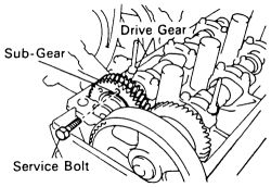
Fig. Fig. 11: Turn the crankshaft pulley so that the hole in the sub-gear (which sets the sub-gear to the camshaft drive gear) comes up
| |
Fig. Fig. 12: Secure the sub-gear to the driven gear with a service bolt
| |
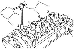
Fig. Fig. 13: Uniformly loosen and remove the 8 bearing cap bolts in several passes in this order
| |
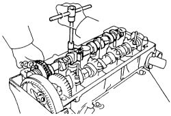
Fig. Fig. 14: Alternately loosen the camshaft cap bolts with the camshaft gear pulled up if necessary
Since the thrust clearance of the camshaft is small, the camshaft must be kept level while it is being removed. If the camshaft is not kept level, the portion of the cylinder head receiving the shaft thrust may crack or be damaged, causing the camshaft to seize or break. To avoid this, the following steps must be carried out.
- Turn the crankshaft pulley so that the hole in the sub-gear (which sets the sub-gear to the camshaft drive gear) comes up. This will allow the No. 1 and No. 3 cylinder cam lobes of the intake camshaft to push their valve lifters evenly.
- Remove the 2 bolts and the No. 1 bearing cap.
-
Secure the intake camshaft sub-gear to the drive gear with a service bolt. The recommended bolt size is:
Thread diameter: 6mmThread pitch: 1.0mmBolt length: 0.63-0.79 in. (16-20mm)
When removing the camshaft, make sure that the torsional spring force of the sub-gear has been eliminated by the previous operation.
- Uniformilly loosen and remove the 8 bearing cap bolts in several passes, in the sequence shown in the illustration.
- Remove the 4 bearing caps and camshaft.
If the camshaft is not being lifted out straight and level, reinstall the No. 3 bearing cap with the 2 bolts. Then alternately loosen and remove the bearing cap bolts with the camshaft gear pulled up.
| |
Fig. Fig. 15: Determine the replacement shim size using a micrometer
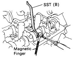
- Remove the adjusting shim with a small flat bladed tool.
-
Determine the replacement adjusting shim size by following the formula or charts.
-
Using a micrometer, measure the thickness of the removed shim. Calculate the thickness of a new shim so that the valve clearance comes within the specified value.
T: Thickness of the remove shimA: Measured value of clearanceN: Thickness of the new shimIntake: N= T + (A - 0.008 in. (0.20mm))
- Select a new shim with a thickness as close as possible to calculate value. The shims are available in 16 sizes in increments of 0.0020 in. (0.05mm). They range from 1.0039 in. (2.55mm to 0.1299 in. (3.30mm).
-
Using a micrometer, measure the thickness of the removed shim. Calculate the thickness of a new shim so that the valve clearance comes within the specified value.
- Install the new adjusting shim by placing the shim on the valve lifter.
- Install the intake camshaft.
| |
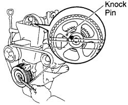
Fig. Fig. 16: Set the exhaust camshaft so that the knock pin is slightly above the top of the cylinder head
| |
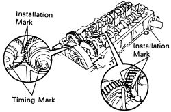
Fig. Fig. 17: Engage the intake camshaft gear to the exhaust gear by matching the installation marks on each gear
| |
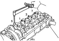
Fig. Fig. 18: Install and tighten uniformly the 8 bearing cap bolts in several passes in this order
Since the thrust clearance of the camshaft is small, the camshaft must be kept level while it is being removed. If the camshaft is not kept level, the portion of the cylinder head receiving the shaft thrust may crack or be damaged, causing the camshaft to seize or break. To avoid this, the following steps must be carried out.
- Turn the crankshaft pulley, set the exhaust camshaft so that the knock pin is slightly above the top of the cylinder head. Apply multi purpose grease to the thrust portion of the camshaft.
- engage the intake camshaft gear to the exhaust camshaft gear by matching the assembly installation mark on each gear.
There are also timing marks (for TDC) on each gear. DO NOT use these marks.
- Roll down the intake camshaft onto the bearing journals while engaging gears with each other. The angle allows the No. 1 and No. 3 cylinder cam lobes of the intake camshaft to push their valve lifters evenly.
- Install the 4 bearing caps in their proper locations. Apply a light coat of engine oil on the threads and under the heads of the bearing cap bolts.
- Install and uniformly tighten the 8 bearing cap bolts in several passes, in the sequence shown to 9 ft. lbs. (13 Nm).
- Remove the service bolt. Install the No. 1 bearing cap with the arrow mark facing forward.
If the No. 1 bearing cap does not fit properly, push the camshaft gear backwards by prying apart the cylinder head and camshaft gear with a flat bladed tool.
- Recheck the valve clearance.
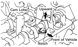
- To adjust the exhaust valve clearance, turn the crankshaft so that the cam lobe of the camshaft on the adjusting valve is upward.
| |
Fig. Fig. 19: Turn the crankshaft so the cam lobe of the camshaft on the adjusting valve is upward, be sure the notch faces the front
| |
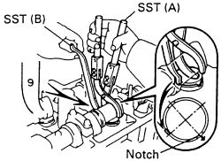
Fig. Fig. 20: Use SST-A to press down the valve lifter, then place SST-B between the camshaft and lifter
| |
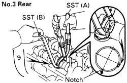
Fig. Fig. 21: Insert the No. 3 rear shim from the exhaust side
| |
Fig. Fig. 22: Remove the shim with a flatbladed tool and a magnetic finger
- Positon the notch of the valve lifter facing the front of the vehicle.
- using a SST-A (09248-05410) or equivalent, press down the valve lifter and place SST-B 909248-05420 (or equivalent), between the camshaft and valve lifter. Remove the SST-A.
Apply SST-B at a slight angle on the side marked with "9", at the position shown in the illustration. When SST-B is inserted too deeply, it will get pinched by the shim. To prevent it from getting stuck, insert it gently from the intake side at a slight angle. The shape of the cam makes it difficult to insert SST-B from the intake side to the No. 3 rear. For this shim, it is best approached from the exhaust side instead.
-
Determine the replacement shim size by following the formula or the chart.
-
Using a micrometer, measure the thickness of the removed shim. Calculate the thickness of a new shim so that the valve clearance comes within the specified value.
T: Thickness of the remove shimA: Measured value of clearanceN: Thickness of the new shimIntake: N= T + (A - 0.008 in. (0.20mm))
- Select a new shim with a thickness as close as possible to calculate value. The shims are available in 16 sizes in increments of 0.0020 in. (0.05mm). They range from 1.0039 in. (2.55mm to 0.1299 in. (3.30mm).
-
Using a micrometer, measure the thickness of the removed shim. Calculate the thickness of a new shim so that the valve clearance comes within the specified value.
- Install the new adjusting shim on the valve lifter. Using the SST-A or equivalent, press down the valve lifter and remove SST-B.
| |
Fig. Fig. 23: Install the new adjusting shim on the valve lifter using SST-A or equivalent
- Recheck the valve clearance.
- Install the valve cover. Tighten the cap nuts to 52 inch lbs. 96 Nm). Attach the spark plug wires.