
HOT IDLE SPEED
Follow the correct service adjustment procedure for your engine. Review the complete procedure before starting.
One of the merits of electronic fuel injection is that it requires so little adjustment. The computer (ECM) does most of the work in compensating for changes in climate, engine temperature, electrical load and driving conditions. The idle on the fuel injected engines should be checked periodically (15,000 miles or 24 months) but not adjusted unless out of specifications by more than 50 rpm.
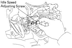
The idle speed adjusting screw is located on the side of the throttle body. You can find the throttle body by following the accelerator cable to its end. The adjusting screw may have a cap over it. If so, pop the cap off with a small screwdriver.
If for any reason the idle cannot be brought into specification by this adjustment procedure, return the screw to its original setting and follow other diagnostic procedures to find the real cause of the problem. Do not try to cure other problems with this adjustment.
4A-F EngineSee Figures 1, 2, 3, 4, 5 and 6
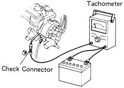
This engine requires a tachometer hook-up to the check connector-see illustrations. NEVER allow the tachometer terminal to become grounded; severe and expensive damage can occur to the coil and/or igniter. Some tachometers are not compatible with this ignition system, confirm the compatibility of your unit before using.
-
Idle speed adjustment is performed under the following conditions:
Air cleaner installedAll pipes and hoses of the intake system connectedAll vacuum lines connected (EVAP, EGR systems ect.)EFI system wiring connectors fully pluggedEngine at normal operating temperatureAccesories switched offTransmission in "N" range
- Connect the tachometer to the engine. Remove the rubber cap and connect the tachometer positive terminal to the check connector at the distributor (IIA).
 |  |
Fig. Fig. 1: Attach the tachometer positive terminal to the check connector at the distributor
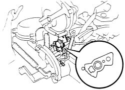
- Set the idle speed by turning the IDLE SPEED adjusting screw. Speed is 650 rpm for manual transmission and 750 rpm's for automatic transmissions.
| |
Fig. Fig. 2: Location of the idle speed adjusting screw
Make adjustments with the engine cooling fan OFF. Leave the tachometer connected for further adjustments.
- To adjust the fast idle speed, shut the engine OFF and remove the air cleaner.
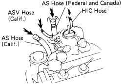
- Plug the AS hose to prevent leakage of the exhaust gases, and plug the HIC hose and ASV hose (California models) to prevent rough idling.
| |
Fig. Fig. 3: Plug the hoses shown
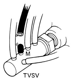
- Disconnect the hose from the TVSV M port and plug the M port. This will shut off the choke opener and EGR system.
| |
Fig. Fig. 4: Disconnect the hose from the TVSV M port and plug the port
- Set the fast idle cam. while holding the throttle valve slightly open, pull up the fast idle cam and hold it closed as you release the throttle valve.
| |
Fig. Fig. 5: Setting the fast idle cam
Check that the fast idle cam is set at the 1 step.
- Start the engine, but DO NOT touch the accelerator pedal.
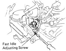
- Set the fast idles speed by turning the fast idle adjustment screw. Speed should be at 3000 rpm's.
| |
Fig. Fig. 6: Turn the screw to set the fast idle
- Install the air cleaner.
See Figure 7
This engine requires a tachometer hook-up to the check connector-see illustrations. NEVER allow the tachometer terminal to become grounded; severe and expensive damage can occur to the coil and/or igniter. Some tachometers are not compatible with this ignition system, confirm the compatibility of your unit before using.
-
Idle speed adjustment is performed under the following conditions:
Engine at normal operating temperatureAir cleaner installedAir pipes and hoses of the air induction and EGR systems properly connectedAll vacuum lines and electrical wires connected and plugged in properlyAll electrical accessories in the OFF positionTransaxle in the N position
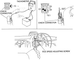
- Connect a tachometer to the engine. Connect the probe of the tachometer to terminal IG- of the check connector.
| |
Fig. Fig. 7: Tachometer installation and idle adjustment-1988-95 4A-FE and 7A-FE engines
- Run the engine at 2500 rpm for 90 seconds.
- Short the check connector at terminals TE1 and E1 using a suitable jumper wire or special service tool 09843-18020.
- Adjust the idle speed by turning the idle speed adjusting screw to specification.
Refer to underhood emission sticker to confirm idle speed specification. Always follow the emission sticker specification.
- Remove the jumper wire or special service tool from the connector terminals.
- Disconnect the tachometer. Road test the vehicle for proper operation.
See Figure 8
-
Idle speed adjustment is performed under the following conditions:
Engine at normal operating temperature.Air cleaner installed.Air pipes and hoses of the air induction and EGR systems properly connected.All vacuum lines and electrical wires connected and plugged in properly.SFI system wiring connectors fully pluggedAll electrical accessories in the OFF position.Ignition timing set correctlyTransaxle in the N position.
- Connect the hand held OBD II scan tool to the DLC3 under the drivers side lower dash panel.
- Race the engine idle speed to 2500 rpm for approximately 90 seconds with the cooling fan off.
- Check the idle speed. If the speed is not correct, check the Idle Air Control (IAC) system.
- Disconnect the OBD II scan tool.
See Figure 8
This engine requires a tachometer hook-up to the check connector-see illustrations. NEVER allow the tachometer terminal to become grounded; severe and expensive damage can occur to the coil and/or igniter. Some tachometers are not compatible with this ignition system, confirm the compatibility of your unit before using.
-
Idle speed adjustment is performed under the following conditions:
Engine at normal operating temperature.Air cleaner installed.Air pipes and hoses of the air induction and EGR systems properly connected.All vacuum lines and electrical wires connected and plugged in properly.All electrical accessories in the OFF position.Transaxle in the N position.
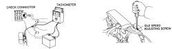
- Connect a tachometer to the engine. Connect the probe of the tachometer to terminal IG- of the check connector.
| |
Fig. Fig. 8: Tachometer installation and idle adjustment-4A-GE engine
- Run the engine at 2500 rpm for 2 minutes.
- Adjust the idle speed by turning the idle speed adjusting screw to specification.
Refer to underhood emission sticker to confirm idle speed specification. Always follow the emission sticker specification.
- Disconnect the tachometer. Road test the vehicle for proper operation.
MIXTURE
The air/fuel ratio burned within the engine is controlled by the ECM, based on information delivered by the various sensors on the engine. It is not adjustable as a routine maintenance item. The easiest way to check the air/fuel mixture is to put the car through a tailpipe emissions test. Whether or not this is required in your area, it's a good way of putting numbers on the combustion efficiency of the engine. The engine can only burn so much fuel; if too much is being delivered, it will show up on the test as unburned hydrocarbons (HC).
Putting the car through this test once a year from the time it is newly acquired can provide an excellent baseline for diagnosing future problems.