
REMOVAL & INSTALLATION 4 A-F Engine
See Figures 1 through 23
 |  |
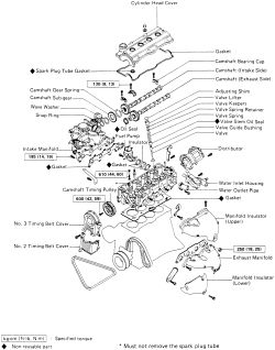
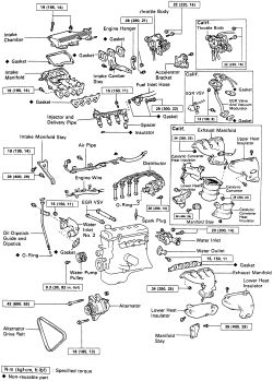
Fig. Fig. 1: Exploded view of the cylinder head assembly-4A-F engine
- Disconnect the negative battery cable.
- Drain the coolant from the radiator and the engine. Drain cocks are located in both.
- Remove the engine under cover. Raising and supporting the vehicle may be required for removal of this component.
- Remove the nuts holding the front exhaust pipe to the manifold.
| |
Fig. Fig. 2: Unbolt the front exhaust pipe from the manifold-4A-F-E engine
- Remove the air cleaner hose and assembly.
- Disconnect the accelerator cable and throttle cable for the automatic transaxles.
| |
Fig. Fig. 3: Disconnect the accelerator and throttle cables from the automatic transaxle
-
Label and unplug the following connectors:
Two accelerator connectionsOil pressure switchA/C pressure switch and A/C connectorEBCV connectorCarburetor connectorsCMH connectorTwo vacuum switch connectorsWater temperature sensorEGR gas temperature sensor connector (Calif.)IIA connectorCooling fan temperature switchOxygen sensor connector
-
Disconnect the following vacuum hoses:
EBCV vacuum hoseVSV of A/C vacuum hoseCharcoal canisterPower steering
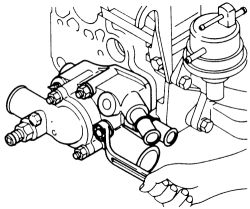
- Disconnect the fuel hoses from the fuel pump.
| |
Fig. Fig. 4: Label and separate the hoses from the mechanical fuel pump-4A-F engine
- Disconnect and set off to the side the upper and lower radiator hoses.
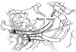
- Unclamp and detach the water hose from the cylinder head rear plate. Disconnect the water by-pass hose.
| |
Fig. Fig. 5: Disconnect the water bypass and cylinder head rear plate hoses
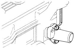
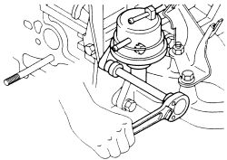
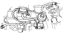
- Remove the water outlet pipe.
| |
Fig. Fig. 6: Unbolt and remove the water outlet pipe
- Remove the bolts retaining the exhaust manifold stay, then unbolt the upper manifold insulator.
- Unbolt and remove the exhaust manifold and lower insulator.
| |
Fig. Fig. 7: Remove the exhaust manifold from the engine-4A-F engine
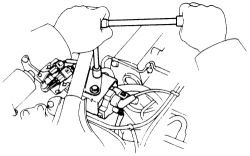
- Remove the distributor.
| |
Fig. Fig. 8: Unbolt and remove the IIA distributor from the engine
- Remove the water inlet housing.
| |
Fig. Fig. 9: Remove the nuts and bolt retaining the inlet water housing
- Unbolt and remove the fuel pump, insulator and gaskets from the engine. discard the old gaskets.
| |
Fig. Fig. 10: Remove the fuel pump mounting bolts and pull the unit off the engine, discard the old gaskets
- Remove the intake manifold.
| |
Fig. Fig. 11: Unbolt the intake manifold from the cylinder head
- Loosen the water pump pulley and remove the drive belt.
- Remove the air pump stay.
- Remove the spark plugs. Remove the valve cover, cap nuts and gasket. Discard the old gasket and cap nuts.
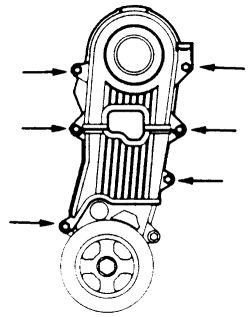
- Unbolt and remove the No. 2 and No. 3 timing belt covers.
| |
Fig. Fig. 12: Remove these retaining bolts from the No. 2 and No. 3 timing bolts
- Set the No. 1 cylinder to TDC of the compression stroke.
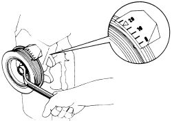
| |
Fig. Fig. 13: Set the No. 1 cylinder to TDC of the compression stroke
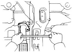
- Remove the No. 3 and No. 2 front covers. Turn the crankshaft pulley and align its groove with the 0 mark on the No. 1 front cover. Check that the camshaft pulley hole aligns with the mark on the No. 1 camshaft bearing cap (exhaust side). If not, rotate the crankshaft 360 degrees until the marks are aligned.
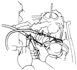
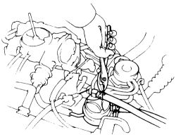
- Remove the plug from the No. 1 front cover and matchmark the timing belt to the camshaft pulley. Loosen the idler pulley mounting bolt and push the pulley to the left as far as it will go; tighten the bolt. Slide the timing belt off the camshaft pulley and support it so it won't fall into the case.
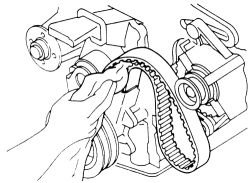
| |
Fig. Fig. 14: Remove the timing belt
- Remove the camshaft pulley and check the camshaft thrust clearance. Remove the camshafts-refer to the necessary service procedures in this section.
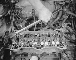
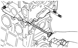
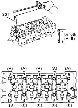
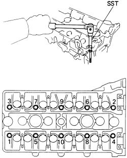
- Gradually loosen the cylinder head mounting bolts in several passes, in the proper sequence. Remove the cylinder head. Discard the old half moons.
| |
Fig. Fig. 15: Gradually loosen the head bolts in several passes-4A-F engine
| |
Fig. Fig. 16: Use a breaker bar to loosen the cylinder head bolts
| |
Fig. Fig. 17: If the head is difficult to remove, pry between the head and block projection
| |
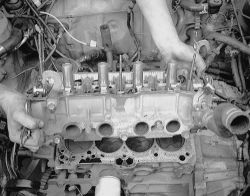
Fig. Fig. 18: Lift the head carefully from the engine
| |
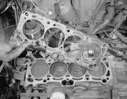
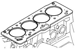
Fig. Fig. 19: ALWAYS discard all old head gaskets
- Install new half moons into the head. They look similar to a half circle made out of rubber.
| |
Fig. Fig. 20: Install new half moons prior to cylinder head installation
- Place a new cylinder head gasket on the block. be careful of the installation direction.
| |
Fig. Fig. 21: Place a new head gasket on the block with the arrows in the correct direction-4A-F engine
Do not mix up the head bolts. They are to be inserted in the exact place they were removed.
| |
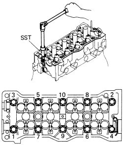
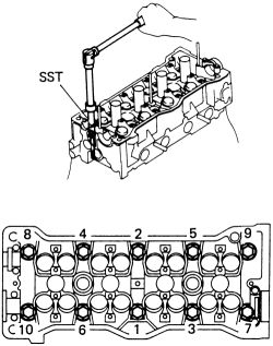
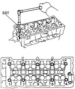
Fig. Fig. 22: Cylinder head bolt tightening sequence-4A-F engine
- Place the cylinder head on top of the gasket. Apply a light coat of engine oil to each bolt thread and under the head of each head bolt. Do not mix up the head bolts.
- Umiformilly tighten each of the ten head bolts in several passes, in the sequence shown. Tighten them to 44 ft. lbs. (60 Nm).
- Assembly and install the camshafts. Gradually tighten the exhaust and intake camshaft bearing cap bolts to 9 ft. lbs. (13 Nm) in proper sequence shown in Camshaft Removal and Installation.
- Install the camshaft timing pulley, tighten the pulley bolt to 43 ft. lbs. (59 Nm). Install the timing belt. Refer to the Timing Belt Removal and Installation procedure later in this section.
-
Inspect the valve clearance. Clearance when cold should be:
Intake: 0.006-0.010 in. (0.15-0.25mm)Exhaust:0.008-0.012 in. (0.20-0.30mm)
- Install the No. 2 and No. 3 timing belt covers.
- Install the valve cover using a new gasket and cap nuts.
- Install the spark plugs. Check the gap prior to installation.
- Attach and secure the air pump stay.
- Attach the water pump pulley and place the drive belt into position.
- Install the intake manifold sing a new gasket. Tighten the nuts and bolts to 14 ft. lbs. (19 Nm). Install the manifold stay and tighten the upper bolt to 14 ft. lbs. (19 Nm). and the lower bolt to 29 ft. lbs. (39 Nm). Attach the water and PCV hoses.
- Install the fuel pump using two new gaskets. Place one gasket into position, insulator, another gasket and the pump. Tighten the mounting bolts till secure.
| |
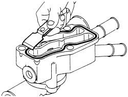
Fig. Fig. 23: Remove all old packing material on the inlet housing with a scraper
-
When installing the water inlet housing, remove any old packing material first. Be careful not to drop any oil on the contact surfaces of the inlet housing or cylinder head.
- Apply sealant 08826-00100 (FIPG) or equivalent to the inlet housing. Avoid applying any excessive amount to the surface. Be especially careful around the oil passages. Components must be assembled within 3 mins. of application. Otherwise the FIPG must be removed and reapplied.
- Install the water inlet housing and tighten to 14 ft. lbs. (19 Nm). Attach the two hoses.
- Install the exhaust manifold. Tighten the manifold nuts and bolts to 18 ft. lbs. (25 Nm) and the stay to 29 ft. lbs. (39 Nm).
- Install the water outlet pipe. Remove any old packing material. Place new FIPG into position and tighten with bolts to 14 ft. lbs. (19 Nm).
- Attach the water hoses, one connects to the cylinder head rear plate and the other is a by pass hose.
- Connect and secure the upper and lower radiator hoses.
- Attach the fuel pump hoses.
- Connect the vacuum hoses and wiring that were labeled and disconnected.
- Attach the accelerator cable and throttle cable for the automatic transaxle.
- Install the air cleaner hose and air cleaner assembly.
- Attach the front pipe to the exhaust manifold.
- Refill the cooling system with coolant. Refer to the Capacities chart.
- Connect the negative battery cable.
- Start the engine, top off the cooling system. Check the oil and coolant levels. inspect for leaks.
- Install the engine undercovers.
- Check the ignition timing. Timing should be 5° BTDC at 900 rpm. with the transaxle in Neutral with the vacuum advance off.
- Recheck the coolant and oil levels.
See Figures 24 through 30
- Disconnect the negative battery cable at the battery. Drain the cooling system.
- Remove the right side engine undercover.
| |
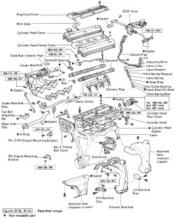
Fig. Fig. 24: Exploded view of the cylinder head removal components-4A-FE and 7A-FE engines
| |
Fig. Fig. 25: Exploded view of the cylinder head removal components (continued)-4A-FE and 7A-FE engines
| |
Fig. Fig. 26: Exploded view of the cylinder head removal components (continued)-4A-FE and 7A-FE engines
- Remove the air cleaner and hoses; disconnect the intake air temperature sensor.
- Disconnect the accelerator and throttle cables at the bracket on vehicles with automatic transaxle.
- Remove the cruise control actuator cable.
- If necessary, remove the alternator and the distributor.
- Disconnect the oxygen sensor wiring at the front pipe. Separate the front pipe from the exhaust manifold.
- Tag and disconnect all wires, lines and hoses that may interfere with exhaust manifold, intake manifold and cylinder head removal.
- Remove the 2 mounting bolts and lift out the exhaust manifold stay. Remove the upper manifold insulator and then remove the exhaust manifold.
- Disconnect the fuel lines. Disconnect the heater hoses at the engine.
- Disconnect the water hose and the bypass hose at the rear of the cylinder head. Remove the 2 bolts and pull off the water outlet pipe.
- Disconnect the 2 water hoses at the water inlet (front of head) and then remove the inlet housing.
- Detach the ground strap connector.
- Disconnect these hoses from the intake chamber; MAP sensor hose, brake booster hose and air hose from the air pipe.
- On models with EGR, remove the Vacuum Switching Valve (VSV).
- Remove the intake manifold stay and the air pipe.
- If necessary, unbolt and remove the throttle body and the air intake chamber.
- Disconnect the PCV, fuel return and vacuum sensing hoses.
- Remove the fuel inlet pipe and the cold start injector pipe (no cold start injector is used on the 1993-97 vehicles). Disconnect the 4 vacuum hoses and then remove the EGR vacuum modulator.
- Remove the fuel delivery pipe along with the injectors, spacers and insulators.
- Unbolt the engine wire cover at the intake manifold, then disconnect the wire at the cylinder head.
- Remove the intake manifold assembly.
- If necessary, remove the RH engine mounting insulator.
- If necessary, remove the drive belts and then remove the water pump pulley.
- Remove the spark plugs, cylinder head cover and semi-circular plug.
-
Remove the No. 3 and No. 2 front covers. Turn the crankshaft pulley and align its groove with the 0 mark on the No. 1 front cover. Check that the camshaft pulley hole aligns with the mark on the No. 1 camshaft bearing cap (exhaust side). If not, rotate the crankshaft 360 degrees until the marks are aligned.
- Remove the plug from the No. 1 front cover and matchmark the timing belt to the camshaft pulley. Loosen the idler pulley mounting bolt and push the pulley to the left as far as it will go; tighten the bolt. Slide the timing belt off the camshaft pulley and support it so it won't fall into the case.
- Remove the camshaft timing pulley.
- Unbolt and remove the alternator bracket and two engine hangers.
- If necessary, remove the oil dipstick guide and dipstick. Discard the old O-ring from the guide. Disconnect the Crankshaft Position Sensor (CPS) wiring.
- On some models there is a second water inlet, unbolt and remove.
- Remove the camshafts-refer to the necessary service procedures in this section.
- Remove the half moon rubber plug. Discard and replace with a new one.
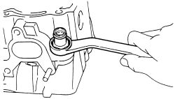
- Gradually loosen the 10 cylinder head mounting bolts in several passes, in the proper sequence. Remove the cylinder head.
| |
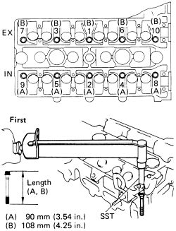
Fig. Fig. 27: Cylinder head bolt removal sequence-4A-FE and 7A-FE engines
The cylinder head bolts on the intake side of the cylinder head are (A) 3.54 in. (90mm) and the bolts on the exhaust side of the head are (B) 4.25 in. (108mm). Label the bolts to ensure proper installation.
To install: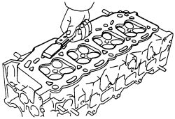
| |
Fig. Fig. 28: Clean the cylinder head and block surfaces
- Clean all the gasket mating surfaces on the cylinder head and block.
- Position the cylinder head on the block with a new gasket. Lightly coat the cylinder head bolts with engine oil and then install them. On 1988-92 vehicles, tighten the bolts in 3 stages, in the proper sequence. On the final pass, tighten the bolts to 44 ft. lbs. (60 Nm).
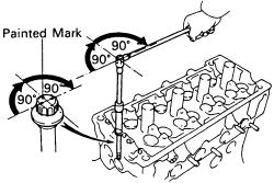
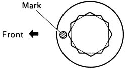
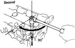
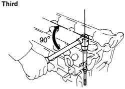
- On the 1993-97 vehicles, coat the head bolts with engine oil and tighten them in several passes, in the sequence shown, to 22 ft. lbs. (29 Nm). Mark the front of each bolt with a dab of paint and then retighten the bolts a further 90° turn. The paint dabs should now all be at a 90° angle to the front of the head. Retighten the bolts one more time a further 90° turn. The paint dabs should now all be pointing toward the rear of the head.
| |
Fig. Fig. 29: Cylinder head bolt tightening sequence-4A-FE and 7A-FE engines
| |
Fig. Fig. 30: On the 1993-97 models, tighten the head bolts the last two passes at 90° turns
- Install the camshafts as outlined in this section.
- Check and adjust the valve clearance. Refer Valve adjustment in .
- Install the water inlet No. 2 and tighten the retainers to 11 ft. lbs. (15 Nm). Attach the inlet hose.
- Install and tighten the engine hangers to 20 ft. lbs. (27 Nm), the fan adjusting bar to 14 ft. lbs. (20 Nm); and the generator bracket to 20 ft. lbs. (26 Nm) if removed.
- If removed install the oil dipstick, apply a small amount of engine oil to the new O-ring and place on the end of the tube. Insert the dipstick gauge into the tube and attach the tube with the mounting bolt and tighten to 82 inch lbs. (9 Nm).
- Engauge the electrical connection to the CPS. Install the alternator bracket and tighten the bolts to 20 ft. lbs. (26 Nm).
- Install the camshaft timing pulley and timing belt, refer to Timing Belt and Sprockets Removal and Installation later in this section.
- Check the valve timing as follows:
Always turn the crankshaft clockwise.
- Loosen the idler pulley bolt half a turn, then turn the crankshaft pulley 2 full revolutions from TDC to TDC.
- Check that the pulleys align with the timing marks in the accompanying illustration. If the timing marks do not align, remove the timing belt and reinstall it.
- Tighten the idler pulley bolt to 27 ft. lbs. (37 Nm).
- Check that there is belt tension at the position illustrated, the deflection should be 4.4 ft. lbs. (20N): 0.20-0.24 inch. (5-6mm). If the deflection is not within range, adjust the idler pulley until the desired deflection is achieved.
- Install the No. 2 and No. 3 timing belt covers and tighten the bolts to 65 inch lbs. (7 Nm).
- Install the half moon plug, using a lubricant (FIPG).
- Install the valve cover with a new gasket and cap nuts.
- Install the RH mounting insulator if removed.
- Install the intake manifold. Connect the engine wiring.
- Install the fuel injectors and delivery pipe, air intake chamber and throttle body. Refer to .
- attach the air pipe and fuel hose clamp.
Attach the clamp claw of the fuel hose to the intake manifold.
- Install the intake manifold stay. If equipped with EGR, install the VSV.
- Attach the MAP, brake booster and power steering hoses.
- Engauge the ground strap connector.
- Clean all gasket material on the water inlet. Apply the FIPG seal to the inlet housing assembly.
Avoid applying any excessive amount to the surface. Be especially careful around the oil passages. Components must be assembled within 3 mins. of application. Otherwise the FIPG must be removed and reapplied.
- Install the water inlet and tighten the retainers to 14 ft. lbs. (20 Nm).
- Install the water outlet. Apply the FIPG seal to the inlet housing assembly and tighten the retainers to 14 ft. lbs. (20 Nm).
Avoid applying any excessive amount to the surface. Be especially careful around the oil passages. Components must be assembled within 3 mins. of application. Otherwise the FIPG must be removed and reapplied.
- Install the exhaust manifold and the front exhaust pipe.
- Install the distributor and alternator.
- Engage the accelerator cable bracket to the throttle body.
- Install the air cleaner hose and cap.
- Connect the negative battery cable.
- Fill the cooling system. Check the crankcase and transmission. Start the vehicle and check for leaks. Top off the cooling system.
- Turn the vehicle OFF and install the RH engine under cover. Check the ignition timing.
- Test drive the vehicle to ensure proper operation.
- Recheck the fluids.
See Figures 30 through 43
- Disconnect the negative battery cable. Remove the RH engine undercover. Drain the cooling system and engine oil.
| |
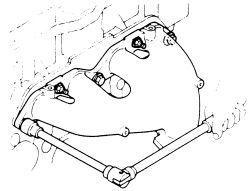
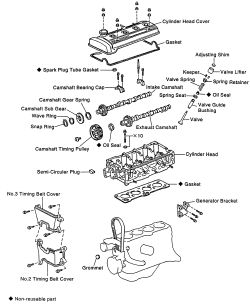
Fig. Fig. 31: Exploded view of the cylinder head components-4A-GE engine
- Loosen the clamp and then disconnect the air cleaner hose from the throttle body. Disconnect the actuator and accelerator cables from the bracket on the throttle body.
| |
Fig. Fig. 32: Remove the air cleaner hose from the throttle body
- If equipped with power steering, remove the power steering pump hoses.
- Remove the water by-pass hoses.
- Remove the washer reservoir.
- Disconnect the brake vacuum hose.
- If equipped with cruise control, remove the actuator.
- Remove the upper radiator hose.
- disconnect the ignition coil wiring. Remove the bolts retaining the coil to the bracket and remove the unit.
| |
Fig. Fig. 33: Unbolt the and remove the ignition coil with bracket-4A-GE engine
- Disengage the engine wire from the No. 4 timing belt cover. Detach the distributor wires, oil pressure sender gauge wire, and compressor wiring for models with A/C.
- Unbolt and pull out the distributor.
- On California models, disconnect the EGR gas temperature sensor connection. Label and separate the hoses from the vacuum pipe. Loosen the bolt and EGR vacuum modulator. Remove the union bolt, four bolts, EGR valve, pipe assembly and gaskets.
| |
Fig. Fig. 34: On California models, remove the EGR valve and modulator-4A-GE engine
- Separate the front pipe from the exhaust manifold.
- Unbolt and remove the exhaust manifold.
- Lable and pull the PCV hose from the valve.
- Remove the cold start injector pipe, delivery pipe and injectors. Refer to .
- Remove the No. 1 fuel pipe with gaskets. from the intake manifold and valve cover. Remove the pressure regulator if equipped.
- Disconnect the No. 2 and No. 3 water by-pass hoses from the auxiliary air valve if equipped.
- Lable and disengage the all engine wiring preventing intake, exhaust manifold, valve cover and cylinder head removal.
- On models with power steering and/or A/C, remove the drive belts.
- Loosen the water pump pulley bolts and the alternator drive belt.
- Remove the water outlet and by-pass pipe. Unbolt the alternator drive belt adjusting bar, water outlet and by-pass assembly. Discard the gaskets.
- Remove the water inlet pipe.
- Remove the RH engine mounting insulator.
- Remove the intake manifold.
- Unbolt and remove the water pump pulley.
- Remove the No. 3 and No. 2 timing belt covers. On models with A/C, remove the idler pulley. Remove the seven mounting bolts, cord support plate, No. 2 and No. 3 covers and gaskets. Discard the old gaskets.
- Remove both valve covers. Discard the old gaskets and cap nuts.
| |
Fig. Fig. 35: Unbolt and remove the valve covers from the cylinder head-4A-GE engine
- Remove the spark plugs.
- Set the No. 1 cylinder to TDC at the compression stroke. Turn the crankshaft pulley and align its groove with the timing mark "0" of the No. 1 timing belt cover. Check that the lifters on the No. 1 cylinder are loose and the valve lifters on the No. 4 cylinder are tight. If not turn the crankshaft one revolution (360°).
- Place matchmarks on the timing belt and 2 timing pulleys. Loosen the idler pulley bolts and move the pulley to the left as far as it will go, then retighten the bolt. Remove the timing belt from the camshaft pulleys.
When removing the timing belt, support the belt so the meshing of the crankshaft timing pulley and the timing belt does not shift. Never drop anything inside the timing case cover. Be sure the timing belt does not come in contact with dust or oil.
- Lock the camshafts and remove the timing pulleys.
- Unbolt and remove the RH mounting brackets.
- Remove the No. 4 timing belt cover.
- Remove the camshafts. Refer to Camshaft Removal and Installation later in this section.
- Remove the No. 2 PCV hose from the cylinder head.
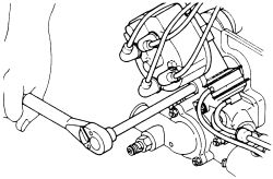
- Loosen the 10 cylinder head bolts gradually in 3 stages, and in the proper order.
| |
Fig. Fig. 36: Cylinder head bolt removal sequence-4A-GE engine
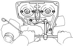
- Lift the cylinder head from the dowels on the block and place the head on wooden blocks on a work bench. Remove the engine hangers and the union.
| |
Fig. Fig. 37: Using a wrench, remove the union from the cylinder head-4A-GE engine
The cylinder head bolts on the intake side of the cylinder head are 3.54 in. (90mm) and the bolts on the exhaust side of the head are 4.25 in. (108mm). Label the bolts to ensure proper installation.
To install:- Clean all the gasket mating surfaces on the cylinder head and block.
- Apply LOCTITE 242 on two or three threads of the union. tighten the union to 22 ft. lbs. (29 Nm).
- Install the engine hangers and ground strap connector, tighten the hangers to 18 ft. lbs. (25 Nm).
- Position the cylinder head on the block with a new gasket.
- After coating the head bolts with engine oil, install and tighten the head bolts in several passes, in the sequence shown to 22 ft. lbs. (29 Nm). Mark the front of each bolt with a dab of paint and then retighten the bolts a further 90° turn. The paint dabs should now all be at a 90° angle to the front of the head. Retighten the bolts one more time a further 90° turn. The paint dabs should now all be pointing toward the rear of the head.
| |
Fig. Fig. 38: Cylinder head bolt tightening sequence-4A-GE engine
| |
Fig. Fig. 39: First, mark the front cylinder head bolt with paint-4A-GE engine
| |
Fig. Fig. 40: Second, retighten the head bolts 90° in tightening sequence-4A-GE engine
| |
Fig. Fig. 41: Third, again retighten the bolts, then check that the paint mark is now facing rearward-4A-GE engine
- Connect the PCV hose to the cylinder head. Install the two clamps.
- Position the camshafts into the cylinder head as described in Camshaft Removal and Installation.
- Install the No. 4 timing belt cover, tighten the retaining bolts to 82 inch lbs. (9 Nm).
| |
Fig. Fig. 42: Install and tighten the No. 4 timing belt cover to 82 inch lbs.-4A-GE engine
- Install the RH mounting brackets, tighten the one bracket with three bolts to 29 ft. lbs. (39 Nm) and the No. 2 bracket to 15 ft. lbs. (21 Nm).
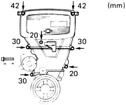
- Install the camshaft timing pulleys, lock each camshaft and tighten the pulley bolts; 1988-89 models 34 ft. lbs. (47 Nm), 1990-91 models 43 ft. lbs. (59 Nm).
- Install the timing belt. Check the valve timing and timing belt deflection. Refer to the Timing Belt Removal and Installation procedure later in this section.
| |
Fig. Fig. 43: Tighten the No. 2 and No. 3 timing belt cover bolts to these specifications-4A-GE engine
-
Inspect the valve clearance. Clearance when cold should be:
Intake: 0.006-0.010 in. (0.15-0.25mm)Exhaust:0.008-0.012 in. (0.20-0.30mm)
- Install the No. 2 and No. 3 timing belt covers. Check the illustration as per bolt installation. On models with A/C, install the idler pulley.
- Temporarily install the water pump pulley.
- Install the valve covers using a new gaskets and cap nuts. Tighten the valve covers to 9 ft. lbs. (13 Nm).
- Install the water outlet with the No. 1 by-pass hose. tighten the cylinder head side bolts to 20 ft. lbs. (27 Nm) and the block side to 9 ft. lbs. (13 Nm).
- Install the spark plugs. Check the gap prior to installation.
- Install the intake air control valve and intake manifold, tighten the manifold mounting bolts to 20 ft. lbs. (27 Nm). Tighten the stay: 12mm bolts to 16 ft. lbs. (22 Nm) and the 14mm bolts to 29 ft. lbs. (39 Nm).
- Install the RH engine mounting insulator. Install the water inlet pipe.
- If removed, install and secure the vacuum switching valve and vacuum tank; and attach the hoses.
- Install the drive belts and tighten the water pump pulley bolts.
- Install the delivery pipe with injectors. Make sure new O-rings are installed on each injector. Refer to .
- Attach the engine wiring to the intake manifold.
- Install the cold start injector pipe and attach any wiring.
- If equipped, install and secure the EGR valve with pipes. Tighten the union bolt to 51 ft. lbs. 969 Nm) and the bolt to 14 ft. lbs. (19 Nm). Attach the EGR modulator. Connect the EGR gas temperature sensor wiring.
- Attach the PCV hose and install the exhaust manifold. Connect the front pipe to the exhaust manifold.
- If removed, attach the brake booster vacuum hose and install the washer tank.
- Install the distributor and coil.
- Connect the actuator and accelerator cables to the bracket on the throttle body.
- Attach the air cleaner hose to the throttle body. Install the air cleaner assembly.
- Connect the negative battery cable.
- Fill the cooling system. Check the crankcase and transmission. Start the vehicle and check for leaks. Top off the cooling system.
- Turn the vehicle OFF and install the RH engine under cover. Check the ignition timing.
- Test drive the vehicle to ensure proper operation.
- Recheck the fluids.