
REMOVAL & INSTALLATION 4A-F, 4A-FE and 4A-GE Engines
See Figures 1 through 7
- Disconnect the negative battery cable.
- Raise and safely support the vehicle.
 |  |
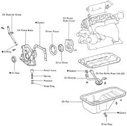
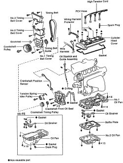
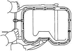
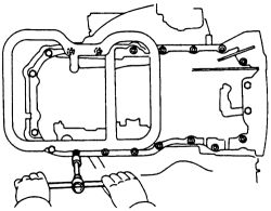
Fig. Fig. 1: Exploded view of the oil pan assembly-4A-F and 4A-GE engines
- Drain the engine oil in a suitable container.
| |
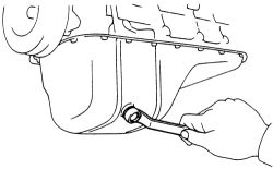
Fig. Fig. 2: Remove the oil pan drain plug to drain the engine oil from the crankcase
- Place a jack under the transaxle to support it.
- Remove the splash shield from under the engine.
- Raise the jack under the transaxle slightly.
- Remove the front pipe from the exhaust manifold and catalyst. Some models have a oxygen sensor, disconnect the wiring.
| |
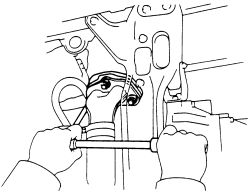
Fig. Fig. 3: Remove the front exhaust pipe to access more room during oil pan removal
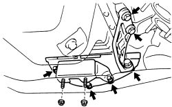
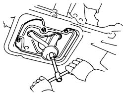
- On the 4A-F and 4A-FE engines, remove the center mounting.
| |
Fig. Fig. 4: Remove the bolts and nuts retaining the center mounting-4A-F engine
- Some 4A-FE engines and all 4A-GE engines are equipped with a stiffener plate. Remove the set bolts and pull the stiffener plate from the vehicle.
- On the 4A-GE engines, unbolt and lower the flywheel housing under cover.
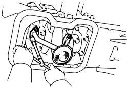
- If equipped, remove the oil cooler hose and union from the oil pan. Remove the two nuts and nineteen bolts retaining the oil pan.
- Insert a blade between the pan and cylinder block, cut off the applied sealer and remove the pan.
| |
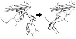
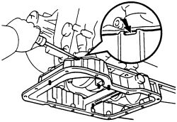
Fig. Fig. 5: Insert a blade and tap lightly to loosen the oil pan free from the block
Be careful not to drop any oil on the contact surfaces of the pan and block.
- Using a razor blade and gasket scraper, remove all traces of packing (FIPG) material from the gasket surfaces. Thoroughly clean all main surfaces to remove loose material. Clean both sealing surfaces with non-residue solvent.
| |
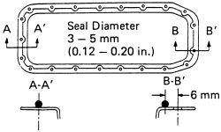
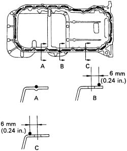
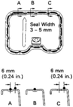
Fig. Fig. 6: Apply a reasonable amount of sealant (FIPG) to the oil pan surface-except 7A-FE engine
- Apply new packing (FIPG) 08826-00080 to the oil pan as shown. Avoid apply excessive amounts to the surface. Be especially careful around the oil passages.
Parts must be assembled within 3 mins of application. Otherwise, the sealer (FIPG) must be removed and reapplied.
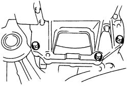
- Install the oil pan over the studs on the block with the nineteen bolts and two nuts. Tighten the bolts to 43 inch lbs. (5 Nm). Make sure when you install the oil pan drain plug, you use a new gasket.
| |
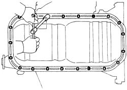
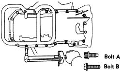
Fig. Fig. 7: Tighten the 19 oil pan retaining bolts securely-4A-F, 4A-FE and 4A-GE engines
- If equipped, install the oil cooler pipe, two new gaskets and union bolt. Tighten the union bolt to 18 ft. lbs. (25 Nm).
- Install the front exhaust pipe (with new gaskets on either end of the pipe) to the manifold.
- On the 4A-GE engines, install and secure the flywheel housing under cover if removed.
- On the 4A-FE engines if removed, attach the stiffener plate. tighten the No. 1 bolt first then the 5 bolts in the sequence shown. Tighten to 17 ft. lbs. (23 Nm).
- On the 4A-GE engines, attach the stiffener plate with the 3 set bolts and tighten them to 27 ft. lbs. (37 Nm).
- Attach the center mounting and tighten the member side bolts to 38 ft. lbs. (52 Nm), plate side to 17 ft. lbs. (23 Nm).
- Lower the jack from the transaxle.
- Lower the vehicle, and fill the crankcase with the appropriate amount of engine oil. Refer to the Capacities chart.
- Connect the negative battery cable, start the engine and check for leaks. If all is well, raise the vehicle slightly and install the engine under cover.
- Recheck the engine oil level, top off if necessary.
See Figures 8 through 17
On the 1993-97 7A-FE engine, a 2 piece oil pan assembly is used. The No. 1 oil pan (upper) is made of aluminum and the No. 2 oil pan (lower) is made of steel. The upper oil pan section is secured to the cylinder block and the transaxle housing, increasing rigidity.
| |
Fig. Fig. 8: Exploded view of the oil pan components-4A-FE and 7A-FE engines
- Disconnect the negative battery cable.
- Raise and safely support the vehicle.
- Drain the engine oil in a suitable container.
- Place a jack under the transaxle to support it.
- Remove the splash shield from under the engine.
- Raise the jack under the transaxle slightly.
- Discxonnect the oxygen sensor wiring at the front pipe. Remove the bolts retaining the front pipe to the mounting bracket. Unbolt the support bracket holding the pipe to the catalyst. Remove the nuts and lower the pipe from the engine.
- Remove the 13 bolts and 2 nuts retaining the No. 2 oil pan. Insert a blade between the pan and the baffle plate. Carefully pry the pan off.
| |
Fig. Fig. 9: Unbolt and lower the No. 2 oil pan-7A-FE engine
- To remove the upper (No. 1) oil pan continue.
- Remove the bolts and nuts retaining the baffle plate.
| |
Fig. Fig. 10: Remove the 2 bolts, nuts and lower the baffle plate from the upper oil pan-7A-FE engine
- Remove the oil strainer and gasket. Discard the old gasket.
| |
Fig. Fig. 11: Remove the oil strainer to access the upper oil pan-7A-FE engine
- Remove the 3 transaxle mounting bolts from the engine rear end plate side. Remove the 6 bolts, the using a 5mm hexagon wrench, remove the 14 bolts securing the No. 1 oil pan. Insert a pry tool between the pan and block and carefully separate the pan from the engine.
| |
Fig. Fig. 12: Unbolt and remove the transaxle mounting from the engine rear end plate side-7A-FE engine
| |
Fig. Fig. 13: Unbolt the upper (No. 1) oil pan ...
| |
Fig. Fig. 14: ... and pry between the block and pan to remove-7A-FE engine
Be careful not to drop any oil on the contact surfaces of the pan and block.
- Using a razor blade and gasket scraper, remove all traces of packing (FIPG) material from the gasket surfaces. Thoroughly clean all mating surfaces to remove loose material. Clean both sealing surfaces with non-residue solvent.
| |
Fig. Fig. 15: Apply a reasonable amount of sealant (FIPG) to the No. 1 oil pan surface-7A-FE engine
- Apply new packing (FIPG) 08826-00080 to the No. 1 oil pan as shown. Avoid apply excessive amounts to the surface. Be especially careful around the oil passages.
Parts must be assembled within 3 mins of application. Otherwise, the sealer (FIPG) must be removed and reapplied.
- Using a 5mm hexagon wrench, install the No. 1 oil pan with 14 NEW bolts. Tighten the bolts (A) to 12 ft. lbs. (16 Nm). Install the 6 bolts (B), and tighten them to 69 inch lbs. (8 Nm).
- Install and tighten the 3 transaxle mounting bolts to the engine rear end plate side and tighten them to 17 ft. lbs. (23 Nm).
- Place a new gasket on the oil strainer and tighten the retaining nuts to 82 inch lbs. (9 Nm).
- Attach the oil pan baffle and tighten the mounting bolts and nuts to 69 inch lbs. (8 Nm).
- Using a razor blade and gasket scraper, remove all traces of packing (FIPG) material from the gasket surfaces. Thoroughly clean all mating surfaces to remove loose material. Clean both sealing surfaces with non-residue solvent.
| |
Fig. Fig. 16: Tighten the No. 1 oil pan bolts to the correct torque-7A-FE engine
- Apply new packing (FIPG) 08826-00080 to the No. 2 oil pan as shown. Avoid apply excessive amounts to the surface. Be especially careful around the oil passages.
| |
Fig. Fig. 17: Apply FIPG to the No. 2 oil pan as shown-7A-FE engine
Parts must be assembled within 3 mins of application. Otherwise, the sealer (FIPG) must be removed and reapplied.
- Attach the No. 2 oil pan and tighten the 13 bolts and 2 nuts to 43 inch lbs. (5 Nm).
- Usaing new gaskets, attach the front exhaust pipe to the manifold and catalyst.
- Lower the jack from the transaxle.
- Lower the vehicle, and fill the crankcase with the appropriate amount of engine oil. Refer to the Capacities chart.
- Connect the negative battery cable, start the engine and check for leaks. If all is well, raise the vehicle slightly and install the engine under cover.
- Recheck the engine oil level, top off if necessary.