
REMOVAL & INSTALLATION 4A-GE Engine
See Figures 1 through 5
- Disconnect the negative battery cable.
 |  |
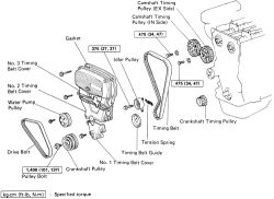
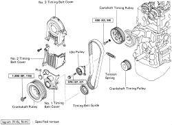
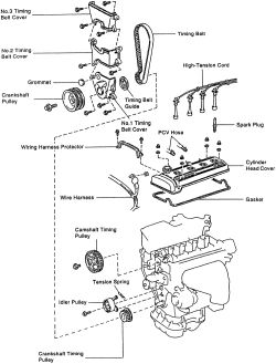
Fig. Fig. 1: Exploded view of the timing belt and cover-4A-GE engine
- Raise the vehicle and safely support it on jackstands.
- Remove the right front wheel.
- Remove the splash shield from under the car.
- Drain the coolant into clean containers. Close the draincocks when the system is empty.
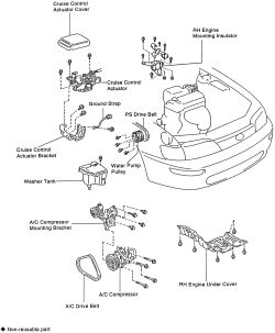
- Lower the car to the ground. Disconnect the accelerator cable and, if equipped, the cruise control cable.
- Remove the cruise control actuator, if equipped.
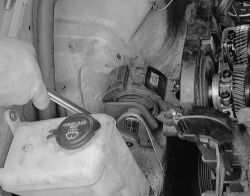
- Remove the washer reservoir.
- Labvel and disconnect the plug wires. Carefully remove the ignition coil.
- Disconnect the radiator hose at the water outlet.
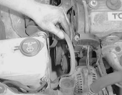
- Remove the power steering drive belt and the alternator drive belt.
- Remove the spark plugs.
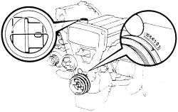
- Rotate the crankshaft clockwise and set the engine to TDC/compression on No. 1 cylinder. Align the crankshaft marks at zero; look through the oil filler hole and make sure the small hole in the end of the camshaft can be seen.
| |
Fig. Fig. 2: Set the No. 1 cylinder to TDC at the compression stroke-4A-GE engine
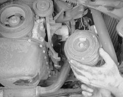
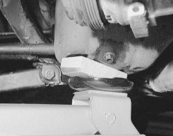
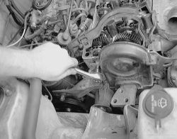
- Raise and safely support the vehicle. Disconnect the center engine mount.
| |
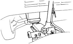
Fig. Fig. 3: Support the engine with a jack and piece of wood when removing the RH engine mounting-4A-GE engine
- Lower the vehicle to the ground.
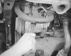
- Support the engine either from above or below. Disconnect the right engine mount from the engine.
- Raise the engine and remove the mount.
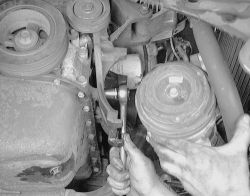
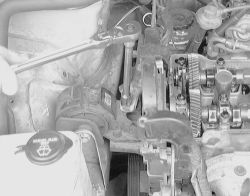
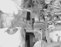
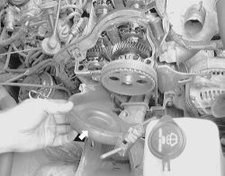
- Unbolt and remove the water pump pulley.
- Remove the crankshaft pulley.
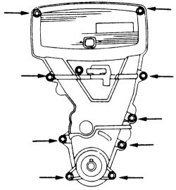
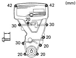
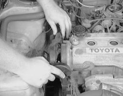
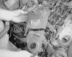
- Remove the 10 bolts and pull off the timing belt covers with their gaskets.
| |
Fig. Fig. 4: Remove the 10 timing belt cover retaining bolt-4A-GE engine
The bolts are different lengths; they must be returned to their correct location at reassembly. Label or diagram the bolts during removal.
To install:When reinstalling, make certain that the gaskets and their mating surfaces are clean and free from dirt and oil. The gasket itself must be free of cuts and deformations and must fit securely in the grooves of the covers.
- Install the gaskets to the belt covers. Place No. 1, No. 2 and No. 3 timing belt covers and support plate into position and secure with the 10 mounting bolts. Be careful of bolt placement. Refer to the illustration for placement.
| |
Fig. Fig. 5: Install the timing belt cover bolts, make sure the correct length bolts are installed-4A-GE engine
- Install the crankshaft pulley, again using the counterholding tool. Tighten the bolt to 101 ft. lbs. (137 Nm).
- Temporarily install the water pump pulley.
- Raise the engine slightly with a jack. Install the right engine mount. Tighten the nut to 38 ft. lbs. (52 Nm) and the through bolt to 64 ft. lbs. (87 Nm). Attach the RH mounting stay and tighten the three bolts to 31 ft. lbs. (42 Nm). Remove the jack.
- Install the spark plugs, tighten 13 ft. lbs. (18 Nm) and attach the plug wires. Install the plug cord cover with bolts.
- Connect the engine wire to the timing belt cover. Attach the following: distributor wiring, oil pressure gauge wiring, ad compressor wiring if equipped with A/C.
- Install the alternator drive belt and the power steering drive belt. Adjust the belts to the correct tension. Attach the water pump pulley and tighten the four bolts.
- Connect the radiator hose to the water outlet port.
- Install the ignition coil.
- Install the cruise control actuator and the cruise control cable, if equipped.
- Connect the accelerator cable.
- Install the washer reservoir tank.
- Refill the cooling system with the correct amount of anti-freeze and water.
- Connect the negative battery cable.
- Start the engine and check for leaks. Allow the engine to warm up and check the work areas carefully for seepage.
- Install the splash shield under the car. Install the right front wheel.
- Test drive the vehicle and top off the coolant level if necessary.
See Figures 6 through 23
- Disconnect the negative battery cable.
| |
Fig. Fig. 6: Exploded view of the timing belt and cover-4A-F engine
- Raise and support the vehicle. Remove the RH wheel and RH engine splash shield.
- Lower the vehicle slightly and support the one side with jackstands. Remove the air cleaner assembly.
- Loosen the water pump pulley bolts and slide off the alternator drive belt. Remove all other drive belts including the compressor if equipped. But do not disconnect any A/C lines. Hang the unit with wire to the side. Remove the compressor bracket also.
| |
Fig. Fig. 7: Remove the drive belts from the engine
| |
Fig. Fig. 8: Loosen the compressor mounting if equipped, do not disconnect any A/C lines
| |
Fig. Fig. 9: Use a piece of wire hang the compressor out of the way
| |
Fig. Fig. 10: Unbolt and remove the compressor mounting bracket
- When removing the power steering pump drive belt, swing the pump as far over as possible to remove the belt.
- On models with A/C, remove the bracket over top of the valve cover and disconnect the harness.
| |
Fig. Fig. 11: Remove the A/C bracket that fits over the top of the valve cover and set aside
- Remove the washer fluid reservoir from the engine compartment.
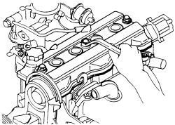
- Remove the valve cover from the cylinder head. Discard all gaskets.
| |
Fig. Fig. 12: Remove the valve cover from the cylinder head-except 4A-GE engine
- Set the No. 1 cylinder to TDC of the compression stroke.
| |
Fig. Fig. 13: Place a piece of wood with a hydraulic jack under the oil pan and raise the engine on the right side
- Remove the RH engine mounting insulator. Set the jack to the engine with a piece of wood between the jack and engine. Remove the mounting bolts and stay. Remove the bolt, two nuts, through bolt and RH mounting.
| |
Fig. Fig. 14: Remove the upper bolts and bracket of the RH engine mount
| |
Fig. Fig. 15: A center bolt under the bracket should be removed ne
| |
Fig. Fig. 16: A through-bolt and two nuts located under the mount are removed last
| |
Fig. Fig. 17: Lift the RH engine mounting off the engine while still supported by the jack
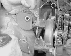
- Remove the water pump pulley.
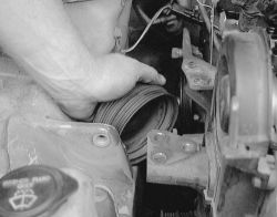
| |
Fig. Fig. 18: Raise the engine slightly more and remove the water pump pulley
When removing the water pump pulley, it may be necessary to raise the engine to slide the pulley off.
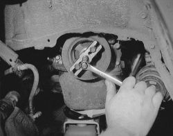
- Using a special tool, retain the crankshaft pulley, then remove the pulley bolt. Remove the crankshaft pulley.
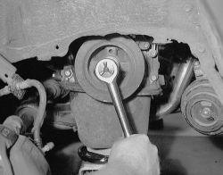
| |
Fig. Fig. 19: Using a special tool, hold the crankshaft pulley, then remove the pulley bolt-4A-F engine
| |
Fig. Fig. 20: Using a gear puller, remove the pulley-4A-F engine
| |
Fig. Fig. 21: Loosen the upper timing cover retaining bolts
| |
Fig. Fig. 22: Pull the upper cover off the front of the engine
- Unbolt the timing belt covers and remove them from the engine.
| |
Fig. Fig. 23: Do the same for the other two timing covers-4A-F engine
When reinstalling, make certain that the gaskets and their mating surfaces are clean and free from dirt and oil. The gasket itself must be free of cuts and deformations and must fit securely in the grooves of the covers.
- Attach the timing belt covers, tighten the mounting bolts.
- Whe installing the crankshaft pulley, apply a light coat of engine oil on the threads and heads under the pulley set bolt. Align the pulley set key with the key groove of the pulley and install. Tighten the mounting bolt to 87 ft. lbs. (118 Nm).
- Temporarily install the water pump pulley.
- With the jack still in position, install the RH engine mounting insulator to the engine mounting bracket. Align the RH insulator with the body bracket and secure with the through bolt and nut. Tighten the bolt to 47 ft. lbs. (64 Nm), the nut to 38 ft. lbs. (52 Nm) and the through bolt to 64 ft. lbs. (87 Nm). Attach the RH mounting stay and tighten the bolts to 31 ft. lbs. (42 Nm). Remove the jack.
- Install the valve cover with a new gasket and cap nuts.
- Place all drive belts into position and adjust.
- Tighten the water pump pulley bolt.
- insatall the air cleaner. RH splash shield and RH wheel.
- Lower the vehicle, check the fluids levels. Connect the negative battery cable.
- Test drive the vehicle.
See Figures 24 and 25
| |
Fig. Fig. 24: Exploded view of the timing belt and cover-4A-FE and 7A-FE engines
| |
Fig. Fig. 25: Exploded view of the timing belt and cover (continued)-4A-FE and 7A-FE engines
- Disconnect the negative battery cable.
- Raise the vehicle and safely support it on jackstands.
- Remove the washer reservoir tank.
- Remove the right splash shield from under the car.
- Remove the RH front wheel. Lower the vehicle.
- Depending on equipment, loosen the air conditioner compressor, the power steering pump and the alternator on their adjusting bolts. Remove the drive belts.
- Disconnect the harness from the ground wire on the RH fender apron.
- Support the engine either from above (chain hoist) or below (floor jack and wood block) and remove the through bolt at the right engine mount.
- Carefully elevate the engine enough to gain access to the water pump pulley.
- Remove the water pump pulley. Lower the engine to its normal position.
- Remove the valve cover. Make sure to label all hoses and wiring.
- Remove the bolts retaining the No. 3 and No. 2 timing belt covers.
- Remove the crankshaft pulley.
- Remove the three bolts retaining the (No. 1) lower timing belt cover. Separate the cover from the front of the engine. Remove the timing belt guide.
- Install the No. 1 timing cover and tighten the mounting bolts to 65 inch lbs. (7 Nm).
- Temporoily install the crankshaft pulley, and align its groove with the timing mark "0" of the No. 1 timing belt cover.
- Install the No. 2 and No. 3 timing belt covers, tighten the bolts to 65 inch lbs. (7 Nm).
- Install the crankshaft pulley by aligning the set key with the key groove of the pulley, the slide the component on. Tighten the pulley bolt to 87 ft. lbs. (118 Nm).
- Install the valve cover using new gaskets and cap nuts.
- Temporarily install the water pump pulley.
- Install the RH engine mounting insulator. Refer to the Torque Specifications chart at the beginning of this section.
- Attach the engine ground connection on the RH fender apron.
- Install and adjust the drive belts.
- Install the RH engine splash shield, front wheel, cruise control actuator and washer tank.
- Check the fluid levels, connect the negative battery cable and start the engine. Check for leaks and test drive.