
REMOVAL & INSTALLATION
Timing belts must always be handled carefully and kept completely free of dirt, grease, fluids and lubricants. This includes any accidental contact from spillage. These same precautions apply to the pulleys and contact surfaces on which the belt rides. The belt must never be crimped, twisted or bent. Never use tools to pry or wedge the belt into place. Such actions will damage the structure of the belt and possibly cause breakage. The timing belt should be replaced at 60,000 miles if the vehicle is used for severe service: towing, repeated short trips in cold weather, extended idling or low speed driving for long distances, etc.
4A-GE EngineSee Figures 1 through 11
- Disconnect the negative battery cable. Remove the timing belt covers.
- Remove the timing belt guide from the crankshaft pulley.
 |  |
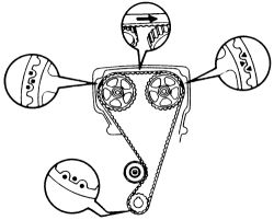
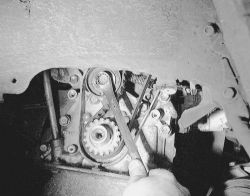
Fig. Fig. 1: Prior to belt removal, inspect all components and matchmark for installation-4A-GE engine
If reusing the timing belt, draw a direction arrow on the belt (in the direction of engine revolution), and place matchmarks on the pulleys and belt.
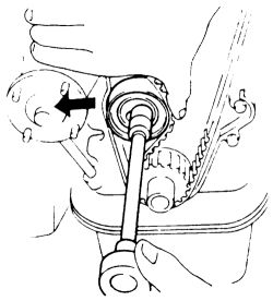
- Loosen the timing belt idler pulley, move it to the left (to take tension off the belt) and tighten its bolt.
| |
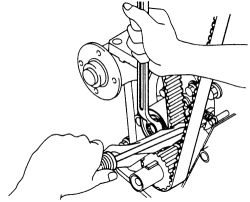
Fig. Fig. 2: Loosen the idler pulley bolt and push it as far to the left as it will go, tighten it, remove the belt ...
- Carefully slip the timing belt off the pulleys.
Do not disturb the position of the camshafts or the crankshaft during removal.
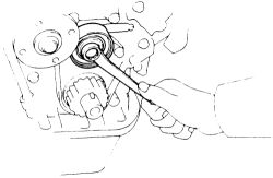
- Remove the idler pulley bolt, pulley and return spring.
| |
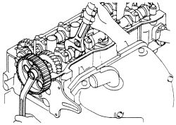
Fig. Fig. 3: ... then remove the idler pulley bolt, pulley, and tension spring-4A-GE engine
- Remove the crankshaft timing pulley.
- Remove the PCV hose and the valve cover.
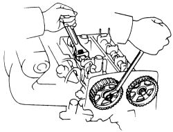
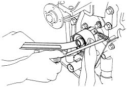
- Use an adjustable wrench to counterhold the camshaft. Be careful not to damage the cylinder head. Loosen the center bolt in each camshaft pulley and remove the pulley. Label the pulleys and keep them clean.
| |
Fig. Fig. 4: Secure the camshaft and remove the pulley bolt
- Check the timing belt carefully for any signs of cracking or deterioration. Pay particular attention to the area where each tooth or cog attaches to the backing of the belt. If the belt shows signs of damage, check the contact faces of the pulleys for possible burrs or scratches.
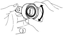
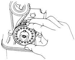
- Check the idler pulley by holding it in your hand and spinning it. It should rotate freely and quietly. Any sign of grinding or abnormal noise indicates the pulley should be replaced.
| |
Fig. Fig. 5: Inspect the smoothness of the idler pulley
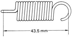
- Check the free length of the tension spring. Correct length is 1.713 inch. (43.5mm) measured at the inside faces of the hooks. A spring which has stretched during use will not apply the correct tension to the pulley; replace the spring.
| |
Fig. Fig. 6: Measure the free length of the tension spring-4A-GE engine
- If you can test the tension of the spring, look for 22 lbs. of tension at 50mm of length. If in doubt, replace the spring.
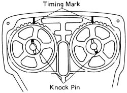
- Align the camshaft knock pin and the pulley. Reinstall the camshaft timing belt pulleys, making sure the pulley fits properly on the shaft and that the timing marks align correctly. Tighten the center bolt on each pulley to 43 ft. lbs.(58 Nm). Be careful not to damage the cylinder head during installation.
| |
Fig. Fig. 7: Position the knock pin of the camshafts as shown-4A-GE engine
- Before reinstalling the belt, double check that the crank and camshafts are exactly in their correct positions. The alignment marks on the pulleys should align with the cast marks on the head and oil pump.
- Reinstall the valve covers with new gaskets and attach PCV hose.
- Install the timing belt idler pulley and its tensioning spring. Move the idler to the left and temporarily tighten its bolt.
- Carefully observing the matchmarks made earlier, install the timing belt onto the pulleys.
- Slowly release tension on the idler pulley bolt and allow the idler to take up tension on the timing belt. DO NOT allow the idler to slam into the belt; the belt may become damaged.
| |
Fig. Fig. 8: Set the No. 1 cylinder to TDC of the compression stroke-4A-GE engine
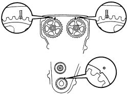
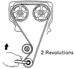
- Temporarily install the crankshaft pulley bolt. Turn the engine clockwise through two complete revolutions, stopping at TDC. Check that each pulley aligns with its marks.
| |
Fig. Fig. 9: Temporarily tighten the crankshaft pulley bolt, then turn it 2 revolutions from TDC to TDC-4A-GE engine
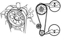
- Check the tension of the timing belt at a top point halfway between the two camshaft sprockets. The correct deflection is 4mm at 4.4 lbs. pressure (2 kg). If the belt tension is incorrect, readjust it by repeating the previous steps. If the tension is correct, tighten the idler pulley bolt to 27 ft. lbs. (37 Nm).
- Remove the crankshaft pulley bolt.
| |
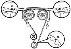
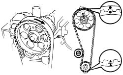
Fig. Fig. 10: Check that each pulley aligns with the timing marks-4A-GE engine
- Install the timing belt guide onto the crankshaft timing pulley. Make sure that the cup side is facing outward.
| |
Fig. Fig. 11: Install the timing belt guide onto the crankshaft pulley, cup side facing outward-4A-GE engine
- Install the timing belt covers. Refer to the Timing Belt Removal and Installation earlier in this section.
See Figures 12 through 22
- Disconnect the negative battery cable.
- Raise and support the vehicle. Remove the RH wheel and RH engine splash shield.
- Lower the vehicle slightly and support the one side with jackstands. Remove the air cleaner assembly.
- Loosen the water pump pulley bolts and slide off the alternator drive belt. Remove all other drive belts.
- Remove the spark plugs.
- Remove the valve cover from the cylinder head. Discard all gaskets.
- Set the No. 1 cylinder to TDC of the compression stroke.
- Turn the crankshaft pulley and align its groove with the No. 1 timing belt cover. Check that the valve lifters on the No. 1 cylinder are loose. If not, turn the crankshaft pulley one complete revolution.
- Remove the RH engine mounting insulator. Set the jack to the engine with a piece of wood between the jack and engine. Remove the mounting bolts and stay. Remove the bolt, two nuts, through bolt and RH mounting.
- Remove the water pump pulley.
- Using a special tool, retain the crankshaft pulley, then remove the pulley bolt. Remove the crankshaft pulley.
- Unbolt the timing belt covers and remove them from the engine.
- Remove the timing belt guide.
| |
Fig. Fig. 12: Draw a direction arrow on the belt (in the direction of revolution) if reusing it-4A-F engine
- To remove the timing belt and idler pulley, loosen the idler pulley bolt. Push it to the left as far as possible, then temporarily tighten it. Remove the timing belt. Now remove the pulley bolt, pulley and return spring.
| |
Fig. Fig. 13: Loosen the idler pulley bolt
| |
Fig. Fig. 14: Push the pulley left as far as it will go, then tighten-4A-F engine
| |
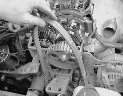
Fig. Fig. 15: Remove the timing belt from above the engine. Note the direction of the arrow
- Remove the crankshaft timing pulley.
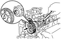
- To remove the camshaft timing pulleys, secure the camshaft and remove the pulley bolt. Be careful not to damage the cylinder head with the wrench.
| |
Fig. Fig. 16: Secure the camshaft and remove the camshaft pulley bolt-4A-F engine
- Check the idler pulley by holding it in your hand and spinning it. It should rotate freely and quietly. Any sign of grinding or abnormal noise indicates the pulley should be replaced.
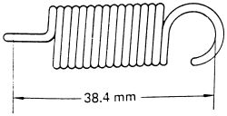
- Check the free length of the tension spring. Correct length is 1.512 inch. (38.4mm) measured at the inside faces of the hooks. A spring which has stretched during use will not apply the correct tension to the pulley; replace the spring.
| |
Fig. Fig. 17: Measure the free length of the tension spring-4A-F engine
When reinstalling, make certain that the gaskets and their mating surfaces are clean and free from dirt and oil. The gasket itself must be free of cuts and deformations and must fit securely in the grooves of the covers.
- Align the camshaft knock pin and camshaft timing pulley. Secure the camshaft and tighten the camshaft timing pulley bolt. Align the bearing cap mark and the center of the small hole on the camshaft timing pulley. Remove any oil or water on the camshaft pulley and keep it clean.
| |
Fig. Fig. 18: Secure the camshaft and tighten the pulley bolt-4A-F engine
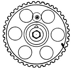
- Install the camshaft timing pulley and align the TDC marks on the oil pump body and crankshaft timing pulley.
| |
Fig. Fig. 19: Align the bearing cap mark and the center small hole on the camshaft timing pulley-4A-F engine
| |
Fig. Fig. 20: Align the marks on the oil pump body and crankshaft timing pulley-4A-F engine
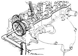
- Temporarily install the timing belt idler pulley with the mounting bolt. Install the tension spring. Pry the timing belt idler pulley toward the left as far as it will go and temporarily tighten it.
| |
Fig. Fig. 21: Install the idler pulley and tension spring, prying the pulley toward the left-4A-F engine
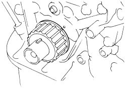
- Install the timing belt.
| |
Fig. Fig. 22: Install the timing belt. Remember the direction arrow-4A-F engine
- Check the valve timing and belt tension. Loosen the timing belt idler pulley mounting bolt. Temporarily install the crank pulley bolt and turn the crankcase two revolutions clockwise from TDC to TDC. Check the valve timing. Insure that each pulley aligns with the marks as shown in the illustration.
- Tighten the timing belt idler pulley bolt to 27 ft. lbs. (37 Nm). Remove the temporarily install cranks pulley bolt.
- Measure the timing belt deflection at the SIDE point, looking for 0.20-0.24 inch (5-6mm) of deflection at 4.4 pounds of pressure (2 kg). If the deflection is not correct, readjust the idler pulley.
- Install the timing belt guide facing the cup side outward.
- Attach the timing belt covers, tighten the mounting bolts.
- Whe installing the crankshaft pulley, apply a light coat of engine oil on the threads and heads under the pulley set bolt. Align the pulley set key with the key groove of the pulley and install. Tighten the mounting bolt to 87 ft. lbs. (118 Nm).
- Temporarily install the water pump pulley.
- With the jack still in position, install the RH engine mounting insulator to the engine mounting bracket. Align the RH insulator with the body bracket and secure with the through bolt and nut. Tighten the bolt to 47 ft. lbs. (64 Nm), the nut to 38 ft. lbs. (52 Nm) and the through bolt to 64 ft. lbs. (87 Nm). Attach the RH mounting stay and tighten the bolts to 31 ft. lbs. (42 Nm). Remove the jack.
- Insatall the valve cover with a new gasket and cap nuts.
- Install the spark plugs, tighten them, to 13 ft. lbs. (18 Nm).
- Place all drive belts into position and adjust.
- Tighten the water pump pulley bolt.
- insatall the air cleaner. RH splash shield and RH wheel.
- Lower the vehicle, check the fluids levels. Connect the negative battery cable.
- Test drive the vehicle.
See Figures 23 and 24
- Disconnect the negative battery cable.
- Raise the vehicle and safely support it on jackstands.
- Remove the washer reservoir tank.
- Remove the right splash shield from under the car.
- Remove the RH front wheel. Lower the vehicle.
- Depending on equipment, loosen the air conditioner compressor, the power steering pump and the alternator on their adjusting bolts. Remove the drive belts.
- Disconnect the harness from the ground wire on the RH fender apron.
- Support the engine either from above (chain hoist) or below (floor jack and wood block) and remove the through bolt at the right engine mount.
- Carefully elevate the engine enough to gain access to the water pump pulley.
- Remove the water pump pulley. Lower the engine to its normal position.
- Remove the spark plugs.
- Remove the valve covers. Make sure to labile all hoses and wiring.
- Rotate the crankshaft clockwise and set the engine to TDC/compression on No. 1 cylinder. Align the crankshaft marks at zero; look through the oil filler hole and make sure the small hole in the end of the camshaft can be seen.
- Remove the bolts retaining the No. 3 and No. 2 timing belt covers.
If reusing the old timing belt, place matchmarks on the timing belt and the camshaft timing pulley. Also place marks on the timing belt to match the end of the No. 1 timing belt cover.
- Remove the crankshaft pulley.
- Remove the three bolts retaining the (No. 1) lower timing belt cover. Separate the cover from the front of the engine. Remove the timing belt guide.
- Loosen the mounting bolt of the idler pulley and shift it to the left as far as it will go, then temporarily tighten it. Remove the timing belt.
- Remove the idler pulley and tension spring.
- To remove the crankshaft pulley, hold the hexagonal head wrench portion of the camshaft with a wrench, then remove the bolt and timing pulley. Be careful not to damage the cylinder head with the wrench.
- Check the idler pulley by holding it in your hand and spinning it. It should rotate freely and quietly. Any sign of grinding or abnormal noise indicates the pulley should be replaced.
- Check the free length of the tension spring. Correct length is on 4A-FE engine; 1.453 inch. (36.9mm) and 7A-FE engine; 1.252 inch (31.8mm) measured at the inside faces of the hooks. A spring which has stretched during use will not apply the correct tension to the pulley; replace the spring.
- When reinstalling, make certain that the gaskets and their mating surfaces are clean and free from dirt and oil. The gasket itself must be free of cuts and deformations and must fit securely in the grooves of the covers.
-
On the 4A-FE engine do the following:
- Align the camshaft knock pin with the knock pin groove on the pulley side with the K mark, the slide on the timing pulley.
- Align the camshaft knock pin with the knock pin groove of the pulley, and slide on the pulley.
| |
Fig. Fig. 23: Align the camshaft knock pin with the groove on the pulley side with the K mark-4A-FE engine
- Temporarily install the timing pulley bolt. Hold the hexagonal wrench head portion of the camshaft with a wrench, then tighten the timing pulley bolt to 43 ft. lbs. (59 Nm).
- Install the crankshaft pulley. Align the pulley set key with the groove of the pulley. Slide on the timing pulley, facing the flange side inwards.
- Temporarilly install the idler pulley and tension spring. Install the idler pulley with the bolt. Do not tighten the bolt yet. Install the tension spring. Push the pulley toward the left as far as it will go and tighten the bolt.
- Set the No. 1 cylinder to TDC of the compression stroke. Turn the hexagonal wrench head portion of the camshaft, and align the hole of the camshaft timing pulley with the timing mark of the bearing cap. Using the crankshaft pulley bolt, turn the crankshaft and position the key groove of the crankshaft timing pulley upward.
- Install the timing belt on the crankshaft timing pulley. Attach the belt guide, facing the cup side outward.
- Install the No. 1 timing cover and tighten the mounting bolts to 65 inch lbs. (7 Nm).
- Temporoily install the crankshaft pulley, and align its groove with the timing mark "0" of the No. 1 timing belt cover.
If reusing the old belt, support the belt so that the meshing of the crankshaft pulley and the timing belt does not shift. Check that the matchmark on the belt matches the end of the No. 1 cover. Align the matchmarks of the belt and the camshaft timing pulley.
-
Check the valve timing and timing belt tension. Remove the grommet and loosen the timing belt idler pulley mounting bolt.
- Turn the crankshaft pulley 2 revolutions clockwise from TDC to TDC.
- Check that each pulley aligns with the marks as shown in the illustration. If the timing marks do not align, remove the timing belt and reinstall it. Tighten the timing belt idler mounting bolt to 27 ft. lbs. (37 Nm). Install the grommet and the No. 1 timing belt cover.
| |
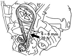
Fig. Fig. 24: Inspect the belt deflection at this position-4A-FE and 7A-FE engines
- Measure the timing belt deflection at the SIDE point, looking for 0.20-0.24 inch (5-6mm) of deflection at 4.4 lbs. pressure (2 kg). If the deflection is not correct, readjust the idler pulley.
- Install the No. 2 and No. 3 timing belt covers, tighten the bolts to 65 inch lbs. (7 Nm).
- Install the crankshaft pulley by aligning the set key with the key groove of the pulley, the slide the component on. Tighten the pulley bolt to 87 ft. lbs. (118 Nm).
- Install the valve cover.
- Install the spark plugs.
- Temporarily install the water pump pulley.
- Install the RH engine mounting insulator. Refer to the Torque Specifications chart at the beginning of this section.
- Attach the engine ground connection on the RH fender apron.
- Install and adjust the drive belts.
- Install the RH engine splash shield, front wheel, cruise control actuator and washer tank.
- Check the fluid levels, connect the negative battery cable and start the engine. Check for leaks and test drive.