
REMOVAL & INSTALLATION
Camshaft end-play (thrust clearance) must be checked before the cam is removed. Please refer to the "inspection'' information for details of this check.
4A-GE EngineSee Figures 1 through 6
- Remove the valve cover and the timing belt covers.
- Make certain the engine is set to TDC/compression on No.1 cylinder. Remove the timing belt following procedures outlined earlier in this section.
- Remove the crankshaft pulley.
- Remove the camshaft timing belt pulleys.
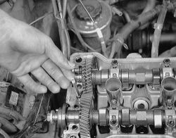
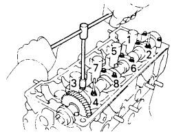
- Loosen and remove the camshaft bearing caps in the proper sequence. It is recommended that the bolts be loosened in two or three passes.
 |  |
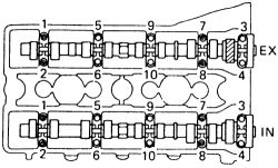
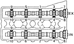
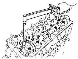
Fig. Fig. 1: Camshaft bearing cap loosening sequence-4A-GE engine
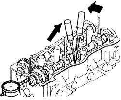
- With the bearing caps removed, the camshaft(s) may be lifted clear of the head. If both cams are to be removed, label them clearly-they are not interchangeable.
Handle the camshaft with care. Do not allow it to fall or hit objects, as it may break into pieces.
To install:- Lubricate the camshaft lobes and journals with clean engine oil.
| |
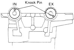
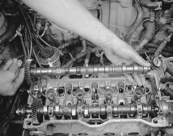
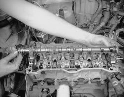
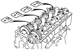
Fig. Fig. 2: Place the camshafts on the cylinder head as shown-4A-GE engine
| |
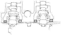
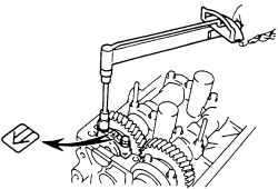
Fig. Fig. 3: Apply seal packing to the head in these positions to the head-4A-GE engine
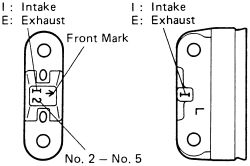
- Place the camshaft(s) in position on the head. The exhaust cam has the distributor drive gear on it. Observe the markings on the bearing caps and place them according to their numbered positions. The arrow should point to the front of the engine.
| |
Fig. Fig. 4: Each bearing cap has its own number and front mark-4A-GE engine
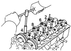
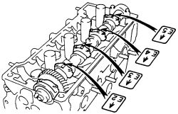
- Tighten the bearing cap bolts in the correct sequence and in three passes to a final tightness of 9 ft. lbs. (12 Nm).
| |
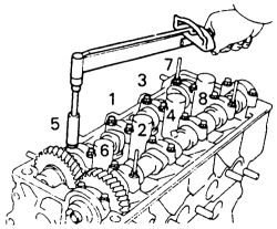
Fig. Fig. 5: Camshaft bearing cap tightening sequence-4A-GE engine
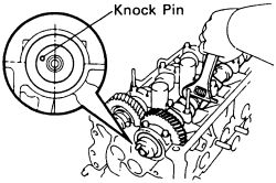
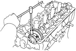
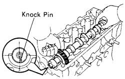
- Position the camshafts so that the guide pins (knock pins) are in the proper position. This step is critical to the correct valve timing of the engine.
| |
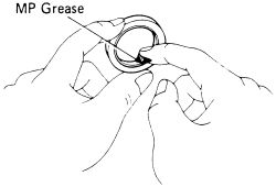
Fig. Fig. 6: Apply multipurpose grease to the new camshaft oil seal lip prior to installation-4A-GE engine
- Install the camshaft timing pulleys and tighten the bolts to 43 ft. lbs. (58 Nm).
- Double check the positioning of the camshaft pulleys and the guide pin.
- Install the crankshaft pulley. Tighten its bolt to 101 ft. lbs. (136 Nm) and double check its position to be on TDC.
- Install the timing belt and tensioner. Adjust the belt according to procedures outlined.
- Install the timing belt covers.
- Install the valve cover.
See Figures 7 through 24
- Remove the valve cover.
- Remove the timing belt covers.
- Remove the timing belt and idler pulley following procedures outlined previously in this section.
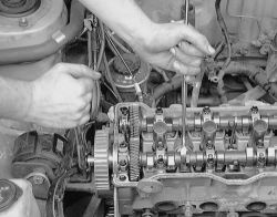
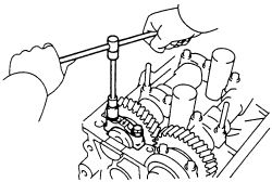
- Hold the exhaust camshaft with an adjustable wrench and remove the camshaft timing belt gear. Be careful not to damage the head or the camshaft during this work.
| |
Fig. Fig. 7: Hold the exhaust camshaft with a wrench and remove the belt gear
| |
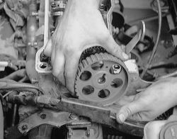
Fig. Fig. 8: Pull the gear off the end of the exhaust cam carefully
| |
Fig. Fig. 9: Set the exhaust camshaft so that the knock pin is slightly above the top of the head-4A-F, 4A-FE and 7A-FE engines
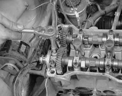
- Gently turn the camshafts with an adjustable wrench until the service bolt hole in the intake camshaft end gear is straight up or in the "12 o'clock'' position.
- Alternately loosen the bearing cap bolts in the number 1 position (closest to the pulley) intake and exhaust bearing caps.
| |
Fig. Fig. 10: Remove the 2 bolts and front bearing cap-4A-F, 4A-FE and 7A-FE engines
| |
Fig. Fig. 11: Loosen the exhaust bearing cap ...
| |
Fig. Fig. 12: ... then the intake cap
| |
Fig. Fig. 13: Secure the intake camshaft sub-gear to the main gear with a service bolt-4A-F, 4A-FE and 7A-FE engines
-
Attach the intake camshaft end gear to the sub gear with a service bolt. The service bolt should be of the following specifications:
Thread diameter: 0.24 inch (6.0mm)Thread pitch: 0.04 inch (1.0mm)Bolt length: 0.63-0.79 inch (16-20mm)
- Uniformly loosen each intake camshaft bearing cap bolt a little at a time and in the correct sequence.
| |
Fig. Fig. 14: Uniformly loosen and remove the 8 intake bearing cap bolts in several passes-4A-F, 4A-FE and 7A-FE engines
The camshaft must be held level while it is being removed. If the camshaft is not kept level, the portion of the cylinder head receiving the shaft thrust may crack or become damaged. This in turn could cause the camshaft to bind or break. Before removing the intake camshaft, make sure the torsional spring force of the sub gear has been removed by installing the bolt in Step 7.
- Remove the bearing caps and remove the intake camshaft.
| |
Fig. Fig. 15: Remove the intake camshaft first
If the camshaft cannot be removed straight and level, retighten the No.3 bearing cap. Alternately loosen the bolts on the bearing cap a little at a time while pulling upwards on the camshaft gear. DO NOT attempt to pry or force the cam loose with tools.
- With the intake camshaft removed, turn the exhaust camshaft approximately 105°, so that the knock pin in the end is just past the "5 o'clock'' position. This puts equal loadings on the camshaft, allowing easier and safer removal.
- Loosen the 2 front exhaust camshaft bearing cap bolts a little at a time and in the correct sequence. Also remove the oil seal.
| |
Fig. Fig. 16: Loosen and remove the front exhaust bearing cap bolts in several passes-4A-F, 4A-FE and 7A-FE engines
- Uniformilly loosen and remove the other 8 exhaust bearing cap bolts in several passes.
| |
Fig. Fig. 17: Uniformly loosen and remove the 8 exhaust bearing cap bolts in several passes-4A-F, 4A-FE and 7A-FE engines
| |
Fig. Fig. 18: Now remove the exhaust camshaft
If the camshaft cannot be removed straight and level, retighten the No. 3 bearing cap. Alternately loosen the bolts on the bearing cap a little at a time while pulling upwards on the camshaft gear. DO NOT attempt to pry or force the cam loose with tools.
- When reinstalling, remember that the camshafts must be handled carefully and kept straight and level to avoid damage.
- Lubricate the camshaft lobes and journals with clean engine oil.
- Place the exhaust camshaft on the cylinder head so that the cam lobes press evenly on the lifters for cylinders No. 1 and 3. This will put the guide pin in the "just past 5 o'clock'' position.
| |
Fig. Fig. 19: Place the exhaust camshaft so that the knock pin is located slightly counterclockwise from the vertical axis of the cam-4A-F, 4A-FE and 7A-FE engines
- Place the bearing caps in position according to the number cast into the cap. The arrow should point towards the pulley end of the engine.
| |
Fig. Fig. 20: Install the 5 exhaust bearing caps in their proper locations-4A-F, 4A-FE and 7A-FE engines
- Tighten the bearing cap bolts gradually and in the proper sequence to 9 ft. lbs. (13 Nm).
| |
Fig. Fig. 21: Uniformly tighten the 10 exhaust bearing cap bolts in several passes-4A-F, 4A-FE and 7A-FE engines
- Apply multi-purpose grease, to a new exhaust camshaft oil seal.
- Install the exhaust camshaft oil seal using a suitable tool. Be very careful not to install the seal on a slant or allow it to tilt during installation.
- Turn the exhaust cam until the cam lobes of No. 4 cylinder press down on their lifters.
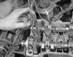
- Hold the intake camshaft next to the exhaust camshaft and engage the gears by matching the alignment marks on each gear.
- Keeping the gears engaged, roll the intake camshaft down and into its bearing journals.
- Place the bearing caps for Nos. 2, 3, 4 and 5 in position. Observe the numbers on each cap and make certain the arrows point to the pulley end of the engine.
| |
Fig. Fig. 22: Intake bearing cap identification-4A-F, 4A-FE and 7A-FE engines
- Gradually tighten each bearing cap bolt in the sequence shown. Tighten each bolt to 9 ft. lbs. (13 Nm).
| |
Fig. Fig. 23: Tightening sequence for the 8 intake bearing cap bolts-4A-F, 4A-FE and 7A-FE engines
- Remove any retaining pins or bolts in the intake camshaft gears.
- Install the No. 1 bearing cap for the intake camshaft with the arrows pointing toward the front.
| |
Fig. Fig. 24: Install and tighten the No. 1 bearing cap on the intake camshaft-4A-F, 4A-FE and 7A-FE engines
If the No. 1 bearing cap does not fit properly, gently push the cam gear towards the rear of the engine by levering between the gear and the head.
- Alternatly tighten the cap bolts a little at a time to 9 ft. lbs. (13 Nm).
- Turn the exhaust camshaft one full revolution from TDC/compression on No. 1 cylinder to the same position. Check that the mark on the exhaust camshaft gear matches exactly with the mark on the intake camshaft gear.
- Counterhold the exhaust camshaft and install the timing belt pulley. Tighten the bolt to 43 ft. lbs. (58 Nm).
- Double check both the crankshaft and camshaft positions, ensuring that they are both set to TDC/compression for No. 1 cylinder.
- Install the timing belt following the procedures outlined.
- Install the timing belt covers and the valve cover.
INSPECTION & MEASUREMENT
See Figures 24, 25, 26, 27 and 28
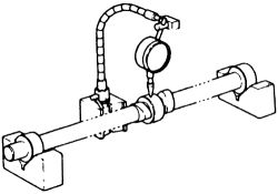
The end-play or thrust clearance of the camshaft(s) must be measured with the camshaft installed in the head. It may be checked before removal or after reinstallation. To check the end-play, mount a dial indicator accurate to ten one-thousandths (four decimal places) on the end of the block, so that the tip bears on the end of the camshaft. The timing belt must be removed. It will be necessary to remove the pulleys for unobstructed access to the camshaft. Set the scale on the dial indicator to zero. Using a screwdriver or similar tool, gently lever the camshaft fore-and-aft in its mounts. Record the amount of deflection shown on the gauge and compare this number to the Camshaft Specifications Chart at the beginning of this section.
| |
Fig. Fig. 25: Checking camshaft end-play with a dial indicator
Excessive end-play may indicate either a worn camshaft or a worn cylinder head; the worn cam is most likely and much cheaper to replace. Chances are good that if the cam is worn in this dimension (axial), substantial wear will show up in other measurements.
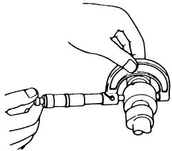
Mount the cam in V-blocks and set the dial indicator up on the center bearing journal. Zero the dial and rotate the camshaft. The circular runout should not exceed 0.0016 in. (0.04mm). Excess runout means the camshaft must be replaced.
| |
Fig. Fig. 26: Use a dial indicator to check the run-out (eccentricity) of the center camshaft bearing
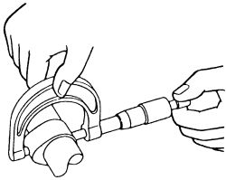
Using a micrometer or Vernier caliper, measure the diameter of all the journals and the height of all the lobes. Record the readings and compare them to the Camshaft Specifications Chart. Any measurement beyond the stated limits indicates wear and the camshaft must be replaced.
| |
Fig. Fig. 27: Use a micrometer to check the camshaft journal diameter
| |
Fig. Fig. 28: Measure the height of each camshaft lobe
Lobe wear is generally accompanied by scoring or visible metal damage on the lobes. Overhead camshaft engines are very sensitive to proper lubrication with clean, fresh oil. A worn camshaft may be your report card for poor maintenance intervals and late oil changes.
On the twin-cam engines, a new camshaft will require readjusting the valves, so new shims are in order.
The clearance between the camshaft and its journals (bearings) must also be measured. Clean the camshaft, the journals and the bearing caps of any remaining oil and place the camshaft in position on the head. Lay a piece of compressible gauging material (Plastigage® or similar) on top of each journal on the camshaft.
Install the bearing caps in their correct order with the arrows pointing towards the front (pulley end) of the engine. Install the bearing cap bolts and tighten them in three passes to the correct tightness of 9 ft. lbs.
Do not turn the camshaft with the gauging material installed.
Remove the bearing caps (in the correct order) and measure the gauging material at its widest point by comparing it to the scale provided with the package. Compare these measurements to the Engine Rebuilding Chart in this section. Any measurement beyond specifications indicates wear. If you have already measured the camshaft (or replaced it) and determined it to be usable, excess bearing clearance indicates the need for a new cylinder head.
Remove the camshaft from the head and remove all traces of the gauging material. Check carefully for any small pieces clinging to contact faces.