
REMOVAL & INSTALLATION
In the process of removing the engine, you will come across a number of steps which call for the removal of a separate component or system, such as "disconnect the exhaust system'' or "remove the radiator.'' In most instances, a detailed removal procedure can be found elsewhere in this guide.
It is virtually impossible to list each individual wire and hose which must be disconnected, simply because so many different model and engine combinations have been manufactured. Careful observation and common sense are the best possible approaches to any repair procedure.
Removal and installation of the engine can be made easier if you follow these basic points:
4A-F Engine
- Disconnect the negative battery cable.
- Remove the battery.
- Remove the hood (mark the hood hinges for correct installation). Have a helper assist you and be careful not to damage the painted bodywork.
- Remove the engine under covers.
- Drain the cooling system, engine and transaxle fluids.
- Removwe the air cleaner and flexible hose.
- Remove the coolant reservoir tank, radiator and fan.
- If equipped with an automatic, disconnect the accelerator and throttle cables at the carburetor.
- Lable and disconnect all electrical wiring and vacuum lines necessary to remove the engine.
- Disconnect the fuel lines at the fuel pump. Plug the lines.
- Disconnect the heater hoses at the water inlet housing.
- Remove the power steering pump and set aside with the lines still attached.
- Remove the air conditioning compressor and set it aside with the refrigerant lines still attached.
- Disconnect the speedometer cable from the transaxle.
- On manual transaxles, remove the slave cylinder and set aside with the hydraulic lines still attached.
- Disconnect the shift control cables.
- Raise and support the vehicle.
- Remove the 2 nuts from the flange then, disconnect the exhaust pipe from the exhaust manifold.
- Disconnect the halfshafts at the transaxle.
- Remove the 2 hole covers, then remove the front, center and rear engine mounts from the center crossmember. Remove the bolts, insulators and center member.
- Attach a suitable hoisting device to the lifting brackets on the engine.
- Remove the bolts and mounting stay. Remove the bolt, nuts and the through-bolt. Next pull out the right side engine mount. Remove the bolts retaining the left mounting stay. Unbolt and remove the left engine mount bracket from the transaxle.
- Inspect and make sure all components are disconnected and labeled. Lift the engine/transaxle assembly out of the vehicle.
- Install the engine in the reverse order of removal paying particular attention to the following.
-
Before reinstalling the engine in the car, several components must be reattached or connected. Install the transaxle to the engine (if separated); tighten the 12mm bolts to 47 ft. lbs. (64 Nm) and the 10mm bolts to 34 ft. lbs. (46 Nm). Tighten all other components to the following specifications:
Starter mounting bolts-29 ft. lbs. (39 Nm)Right motor mount and through bolt-58 ft. lbs. (78 Nm).Engine mounting automatics-38 ft. lbs. (52 Nm)Engine mounting bracket-to-transaxle-45 ft. lbs. (61 Nm)Engine mounting stay LH-15 ft. lbs. (21 Nm)Engine mounting LH-to-transaxle manual-38 ft. lbs. (52 Nm)Engine mounting stay RH-31 ft. lbs. (42 Nm)Engine mounting RH-to-engine manual-nut-38 ft. lbs. (52 Nm)Engine mounting RH-to-engine manual bolt-47 ft. lbs. (64 Nm)Engine mounting bolt front-35 ft. lbs. (48 Nm)Engine mounting bolt center-38 ft. lbs. (52 Nm)Engine mounting bolt rear-42 ft. lbs. (57 Nm)Engine front and rear mounting bolts-58 ft. lbs. (78 Nm)Power steering pump pulley bolt-28 ft. lbs. (38 Nm)Exhaust pipe-to-manifold-46 ft. lbs. (62 Nm)
- Fill the transaxle with the correct amount of oil, and fill the engine with oil.
- Fill the cooling system with the proper amount of fluid.
- Double check all installation items, paying particular attention to loose hoses or hanging wires, untightened nuts, poor routing of hoses and wires (too tight or rubbing) and tools left in the engine area.
- Connect the negative battery cable.
- Start the engine and allow it to reach normal operating temperature. Check carefully for leaks. Shut the engine OFF.
- Raise the front end of the car, support on jackstands and install the splash shields below the car.
- Lower the car to the ground. With your helper, install the hood and adjust it for proper fit and latching. Road test the vehicle for proper operation.
See Figures 1 through 18
- Remove the hood (mark the hood hinges for correct installation). Have a helper assist you and be careful not to damage the painted bodywork.
 |  |
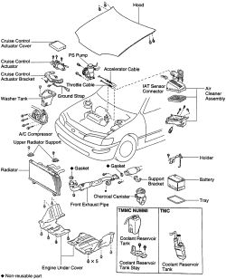
Fig. Fig. 1: Exploded view of the engine removal components-4A-FE and 7A-FE engines
| |
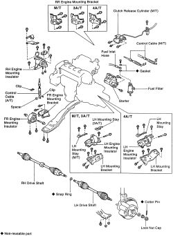
Fig. Fig. 2: Exploded view of the engine removal components (continued)-4A-FE and 7A-FE engines
The fuel system is under pressure. Release pressure slowly and contain spillage. Observe no smoking/no open flame precautions. Have a Class B-C (dry powder) fire extinguisher within arm's reach at all times.
- Relieve the fuel system pressure. Disconnect the negative battery cable, then the positive battery cable and remove the battery.
- Raise the vehicle and safely support it on jackstands.
- Remove the left and right splash shields.
- Drain the engine oil and the transmission oil.
- Drain the engine coolant.
- Disconnect the accelerator cable from the bracket. On automatics disconnect the throttle cable from the accelerator bracket.
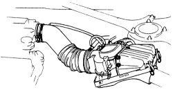
- Remove the air cleaner hose and the air cleaner assembly.
| |
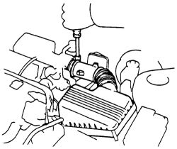
Fig. Fig. 3: Unbolt and remove the air cleaner assembly-4A-FE and 7A-FE engines
- Remove the coolant reservoir. Remove the radiator and fan assembly.
| |
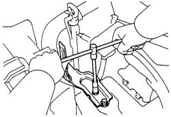
Fig. Fig. 4: Remove the bolts retaining the coolant reservoir stay-4A-FE and 7A-FE engines
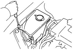
- Remove the washer reservoir tank.
| |
Fig. Fig. 5: Unbolt and pull the washer reservoir from the engine compartment-4A-FE and 7A-FE engines
- Disconnect and remove the cruise control actuator.
- Label and disconnect the main engine wiring harness from its related sensors and switches.
-
Disconnect the following vacuum hoses and connectors from the intake chamber:
- MAP hose from the gas filter
- Brake booster vacuum hose
- A/C vacuum hose from the actuator
- Disconnect the A/C actuator harness
-
Disconnect the following hoses and wiring on the RH fender apron side:
- Gound strap connector
- MAP connector
- A/C pressure switch
- Engine wire from the apron
-
Disconnect the following hoses and wiring on the LH fender apron side:
- DLC1 connector
- Connection from the fender apron
- Ground strap from the fender apron
- Remove the two bolts and engine relay box. Unsecure the four harness connectors from the engine relay box.
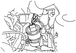
- Remove the charcoal canister.
| |
Fig. Fig. 6: Disconnect the hose and remove the charcoal canister from the bracket-4A-FE and 7A-FE engines
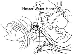
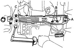
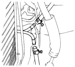
- Disconnect the heater hoses.
| |
Fig. Fig. 7: Disconnect the heater hoses from the water inlet housing and pipe-4A-FE and 7A-FE engines
- Carefully disconnect the fuel inlet and return lines.
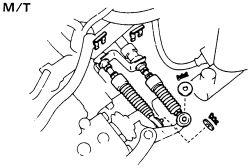
- If equipped with manual transaxle, unbolt the clutch slave cylinder from the bell housing and move the cylinder out of the way. Don't disconnect any lines or hoses. Disconnect the shift control cables by removing the two clips, the washers and retainers.
| |
Fig. Fig. 8: Unbolt and set aside the slave cylinder, DO NOT disconnect the hydraulic lines-4A-FE and 7A-FE engines
| |
Fig. Fig. 9: On manual transaxles, disconnect the shift control cables-4A-FE and 7A-FE engines
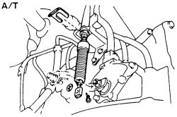
- On automatics, disconnect the control cable from the shift lever by unsecuring the clip and retainer.
| |
Fig. Fig. 10: On automatic transaxles, disconnect the control cable from the shift ever-4A-FE and 7A-FE engines
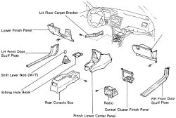
- Disconnect the engine wiring from the cabin. Remove both door scuff plates, the lower panel with glove box door, radio, center console cluster finish panel, rear console box and detach any associated wiring. Disconnect the wiring from the ECU and pull the harness out through the cowl panel.
| |
Fig. Fig. 11: Exploded view of the removal components in the cabin-4A-FE and 7A-FE engines
- Loosen the power steering pump mounting bolt and through bolt. Remove the drive belt.
- Remove the four bolts holding the air conditioner compressor and remove the compressor. DO NOT loosen or remove any lines or hoses. Move the compressor out of the way and hang it from a piece of stiff wire.
- Disconnect the speedometer cable from the transaxle.
- Disconnect the oxygen sensor. Remove the two bolts from the exhaust pipe flange and separate the pipe from the exhaust manifold.
- Raise the car and support it safely on jackstands.
- On 4WD models, disconnect the oil cooler hoses.
- Remove the nuts and bolts and separate the halfshafts from the transaxle.
- On 4WD models, disconnect the propeller shaft.
- Remove the through bolt from the rear transaxle mount.
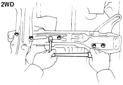
- Remove the nuts from the center transaxle mount and the rear mount.
| |
Fig. Fig. 12: Removing the 2WD center member mounting-4A-FE and 7A-FE engines
| |
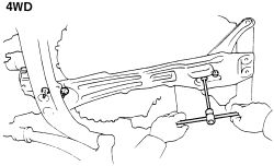
Fig. Fig. 13: Removing the 4WD center member mounting-4A-FE engine
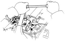
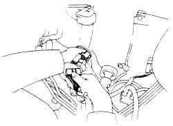
- Lower the vehicle to the ground and attach the lifting equipment to the brackets on the engine. Take tension on the hoist line or chain just enough to support the engine but no more. Hang the engine wires and hoses on the chain or cable.
- Remove the three exhaust hanger bracket nuts and the hanger. Remove the two center crossmember-to-main crossmember bolts. Remove the three center crossmember-to-radiator support bolts.
- On 4WD models, remove the eight crossmember-to-body bolts, then remove the two bolts holding the control arm brackets to the underbody. Remove the two center mount-to-transaxle bolts and remove the mount. Carefully lower the center mount and crossmember and remove from under the car.
| |
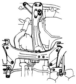
Fig. Fig. 14: 4WD front suspension crossmember mounting-4A-FE engine
- At the left engine mount, remove the three bolts and the bracket, then remove the bolt, two nuts, through bolt and mounting. Remove the three bolts and the air cleaner bracket.
- Loosen and remove the five bolts and disconnect the mounting bracket from the transaxle bracket. Remove the through bolt and mounting.
- Carefully and slowly raise the engine and transaxle assembly out of the car. Tilt the transaxle down to clear the right engine mount. Be careful not to hit the steering gear housing. Make sure the engine is clear of all wiring, lines and hoses.
| |
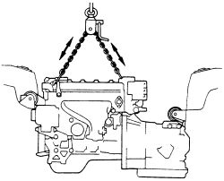
Fig. Fig. 15: Carefully attach a chain hoist to the engine hangers and lift the assembly out-4A-FE and 7A-FE engines
- Support the engine assembly on a suitable stand; do not allow it to remain on the hoist for any length of time.
- With the engine properly supported, disconnect the reverse light switch and the neutral safety switch (automatic transaxle).
- Remove the rear end cover plate.
- If equipped with automatic transaxle, remove the 6 torque converter mounting bolts.
- Remove the starter.
- Support the transaxle, remove the retaining bolts in the case and remove the transaxle from the engine. Pull the unit straight off the engine; do not allow it to hang partially removed on the shaft. Keep the automatic transaxle level; if it tilts forward the converter may fall off.
- Before reinstalling the engine in the vehicle, several components must be reattached or connected.
- Attach the chain hoist or lift apparatus to the engine and lower it into the engine compartment.
Tilt the transaxle downward and lower the engine to clear the left motor mount. As before, be careful not to hit the power steering housing (rack) or the throttle position sensor.
-
Level the engine and align each mount with its bracket. Installation is the reverse of removal for engine installation. Tighten the components to the following specifications on 1988-92 models:
RH mounting insulator-to-engine bracket bolt-47 ft. lbs. (64 Nm)RH mounting insulator-to-engine bracket nut-38 ft. lbs. (52 Nm)RH insulator-to-body bracket-64 ft. lbs. (87 Nm)LH insulator-to-transaxle case bracket-35 ft. lbs. (48 Nm)RH mounting stay-31 ft. lbs. (42 Nm)LH mounting stay-15 ft. lbs. (21 Nm)Engine center member front and rear mounting bolt-64 ft. lbs. (87 Nm)Engine center member 5 bolts-45 ft. lbs. (61 Nm)4WD front crossmember lower control arm-152 ft. lbs. (206 Nm)4WD front crossmember rear bolt-94 ft. lbs. (127 Nm)Front mounting-to-member-35 ft. lbs. (48 Nm)Center (2WD) mounting-to-center-38 ft. lbs. (52 Nm)Rear (2WD) mounting-to-member-38 ft. lbs. (52 Nm)Rear (4WD) mounting-to-member-42 ft. lbs. (57 Nm)Front pipe-to-exhaust manifold-46 ft. lbs. (62 Nm)
Tighten the components to the following specifications on 1993-97 models:

| |
Fig. Fig. 16: Tighten the RH insulator-to-body and bracket bolts-1993-95 4A-FE and 7A-FE engines
| |
Fig. Fig. 17: Tighten the RH insulator-to-body and bracket bolts-1996-97 4A-FE and 7A-FE engines
| |
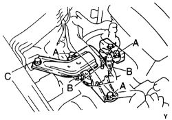
Fig. Fig. 18: Tighten the bolts retaining the center member to the body-4A-FE and 7A-FE engines
- Install the battery. Connect the positive cable to the starter terminal, then to the battery. DO NOT connect the negative battery cable at this time.
- Fill the transmission with the correct amount of fluid.
- Refill the engine coolant.
- Fill the engine with the correct amount of oil.
- Double check all installation items, paying particular attention to loose hoses or hanging wires, untightened nuts, poor routing of hoses and wires (too tight or rubbing) and tools left in the engine area.
- Connect the negative battery cable. Start the engine and allow it to idle. As the engine warms up, shift the automatic transmission into each gear range allowing it to engage momentarily. After each gear has been selected, put the shifter in PARK and check the transmission fluid level.
- Shut the engine OFF and check the engine area carefully for leaks, particularly around any line or hose which was disconnected during removal.
- Raise and support the front end of the car on jackstands. Replace the left and right splash shields and lower the vehicle.
- With the help of an assistant, reinstall the hood. Adjust the hood for proper fit and latching. Road test the vehicle for proper operation.
See Figures 19 through 23
- Relieve the fuel system pressure. Disconnect the negative battery cable.
- With a helper remove the hood (mark hood hinges for correct installation) from the car. Use care not to damage the paint finish on the vehicle.
- Drain the engine oil.
- Drain the cooling system.
- Drain the transaxle oil.
- Remove the air cleaner assembly.
| |
Fig. Fig. 19: Remove the air cleaner assembly-4A-GE engine
- Remove the coolant reservoir tank and remove the PCV hose.
- Label and remove the heater hoses from the water inlet housing.
- Label and disconnect the fuel inlet hose from the fuel filter.
The fuel system is under pressure. Release pressure slowly and contain spillage. Observe no smoking/no open flame precautions. Have a Class B-C (dry powder) fire extinguisher within arm's reach at all times.
- Disconnect the heater and air hoses from the air valve.
- Remove the fuel return hose from the pressure regulator.
- If equipped with a manual transaxle, remove the slave cylinder from the housing. Loosen the mounting bolts and move the cylinder out of the way but do not loosen or remove the fluid hose running to the cylinder.
- Disconnect the vacuum hose running to the charcoal canister.
- Disconnect the shift control cable, the speedometer cable (at the transaxle) and the accelerator cable (at the throttle body).
-
If equipped with cruise control, disconnect the cables. Remove the cruise control actuator by:
- Disconnecting the vacuum hose.
- Removing the cover and the 3 bolts.
- Disconnecting the actuator wiring and removing the actuator.
- Remove the ignition coil.
| |
Fig. Fig. 20: Unbolt and remove the ignition coil-4A-GE engine
-
Remove the main engine wiring harness in the following steps:
- From inside the car, remove the right side cowl (kick) panel.
- Disconnect the wiring harness at junction block 4.
- Remove the cover over the Electronic Control Module (ECM) and carefully disconnect the ECM plugs.
- Pull the main wiring harness into the engine compartment.
| |
Fig. Fig. 21: Pull the engine wiring through the cowl panel-95 4A-FE and 7A-FE engines
- Disconnect the wiring at the number 2 junction block in the engine compartment.
- Remove the engine and transaxle ground straps.
- Disconnect the washer valve harness.
- Remove the wiring at the cruise control vacuum pump harness and the vacuum switch connector.
- Remove the hose from the brake vacuum booster.
-
Depending on equipment, remove the air conditioning compressor and/or the power steering pump. Note that the units are to be removed from their mounts and placed out of the way- DO NOT disconnect hoses and lines from the units.
- Remove the power steering pump pulley nut.
- Loosen the idler pulley adjusting and pulley bolts.
- Remove the four compressor mounting bolts.
- Move the compressor aside and suspend it with stiff wire out of the way.
- Loosen the compressor bracket bolts.
- Disconnect the oil pressure harness.
- Loosen the power steering pump lock bolts and pivot bolts.
- Remove the pump and its bracket; suspend it out of the way with a piece of stiff wire.
- Safely raise the vehicle and support on jackstands. Double check the stands and make sure the vehicle is solidly supported.
- Remove the splash shields under the car.
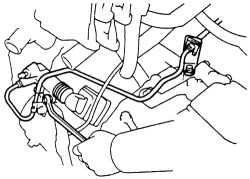
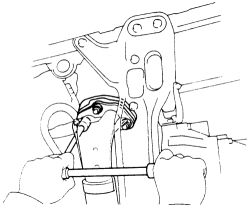
- Disconnect the oil cooler hoses.
| |
Fig. Fig. 22: Disconnect the oil cooler tubes-4A-GE engine
- Disconnect the exhaust pipe from the exhaust manifold.
| |
Fig. Fig. 23: Unbolt and separate the front pipe from the exhaust manifold
- Carefully disconnect the wiring from the oxygen sensor.
- Remove the cover under the flywheel.
- Remove the front and rear motor mounts from the center crossmember.
- Remove the center crossmember.
- Disconnect the right side control arm at the steering knuckle.
- Disconnect the halfshafts from the transaxle.
- Lower the vehicle to the ground. Install the engine hoist to the lifting bracket on the engine. Hang the engine wires and hoses on the lift chain. Take tension on the hoist sufficient to support the engine; double check all hoist attaching points.
- Disconnect the right side engine mount by removing the bolt.
- Disconnect the left side motor mount from the transaxle bracket.
- Lift the engine and transaxle from the vehicle. Be careful to avoid hitting the steering box and the throttle position sensor.
- Support the engine assembly on a suitable stand; do not allow it to remain on the hoist for any length of time.
- Disconnect the radiator fan temperature switch harness.
- Disconnect the start injector time switch.
- Label and remove the vacuum hoses from the Bimetal Vacuum Switching Valves (BVSV).
- Separate the hoses from the water bypass valves, then remove the water inlet housing assembly.
- Label and remove the wiring connectors from the reverse switch, water temperature sensor, and water temperature switch. If equipped with automatic transaxle, remove the wiring to the neutral safety switch and transaxle solenoid.
- If equipped with automatic transaxle, remove the 6 torque converter-to-flexplate bolts.
- Remove the starter along with its cable and connector.
- Support the transaxle, remove the retaining bolts in the case, then separate the transaxle from the engine. Pull the unit straight off the engine; do not allow it to hang partially removed on the shaft. Keep the automatic transaxle level; if it tilts forward the converter may fall off.
- Install the engine in the reverse order of removal paying particular attention to the following.
-
Before reinstalling the engine in the car, several components must be reattached or connected. Install the transaxle to the engine; tighten the 12mm bolts to 47 ft. lbs. (64 Nm) and the 10mm bolts to 34 ft. lbs. (46 Nm). Tighten other components to the following specifications:
Starter mounting bolts-29 ft. lbs. (39 Nm)Right motor mount and through bolt-58 ft. lbs. (78 Nm).Engine mounting automatics-38 ft. lbs. (52 Nm)Engine mounting bracket-to-transaxle-45 ft. lbs. (61 Nm)Engine mounting stay LH-15 ft. lbs. (21 Nm)Engine mounting LH-to-transaxle manual-38 ft. lbs. (52 Nm)Engine mounting stay RH-31 ft. lbs. (42 Nm)Engine mounting RH-to-engine manual-nut-38 ft. lbs. (52 Nm)Engine mounting RH-to-engine manual bolt-47 ft. lbs. (64 Nm)Engine mounting bolt front-35 ft. lbs. (48 Nm)Engine mounting bolt center-38 ft. lbs. (52 Nm)Engine mounting bolt rear-42 ft. lbs. (57 Nm)Engine rear mounting bolt-64 ft. lbs. (87 Nm)Engine front mounting bolt-64 ft. lbs. (87 Nm)Power steering pump pulley bolt-28 ft. lbs. (38 Nm)
- Fill the transaxle with the correct amount of oil, and fill the engine with oil.
- Fill the cooling system with the proper amount of fluid.
- Double check all installation items, paying particular attention to loose hoses or hanging wires, untightened nuts, poor routing of hoses and wires (too tight or rubbing) and tools left in the engine area.
- Connect the negative battery cable.
- Start the engine and allow it to reach normal operating temperature. Check carefully for leaks. Shut the engine OFF.
- Raise the front end of the car, support on jackstands and install the splash shields below the car.
- Lower the car to the ground. With your helper, install the hood and adjust it for proper fit and latching. Road test the vehicle for proper operation.