
See Figures 1, 2, 3 and 4
Most engine overhaul procedures are fairly standard. In addition to specific parts replacement procedures and specifications for your individual engine, this section is also a guide to acceptable rebuilding procedures. Examples of standard rebuilding practice are given and should be used along with specific details concerning your particular engine.
Competent and accurate machine shop services will ensure maximum performance, reliability and engine life. In most instances it is more profitable for the do-it-yourself mechanic to remove, clean and inspect the component, buy the necessary parts and deliver these to a shop for actual machine work.
Much of the assembly work (crankshaft, bearings, piston rods, and other components) is well within the scope of the do-it-yourself mechanic's tools and abilities. You will have to decide for yourself the depth of involvement you desire in an engine repair or rebuild.
TOOLS
The tools required for an engine overhaul or parts replacement will depend on the depth of your involvement. With a few exceptions, they will be the tools found in a mechanic's tool kit (see of this repair guide). More in-depth work will require some or all of the following:
The use of most of these tools is illustrated in this section. Many can be rented for a one-time use from a local parts jobber or tool supply house specializing in automotive work.
Occasionally, the use of special tools is called for. See the information on Special Tools and the Safety Notice in the front of this book before substituting another tool.
OVERHAUL TIPS
Aluminum has become extremely popular for use in engines, due to its low weight. Observe the following precautions when handling aluminum parts:
When assembling the engine, any parts that will be exposed to frictional contact must be prelubed to provide lubrication at initial start-up. Any product specifically formulated for this purpose can be used, but engine oil is not recommended as a prelube in most cases.
When semi-permanent (locked, but removable) installation of bolts or nuts is desired, threads should be cleaned and coated with Loctite® or another similar, commercial non-hardening sealant.
CLEANING
Before the engine and its components are inspected, they must be thoroughly cleaned. You will need to remove any engine varnish, oil sludge and/or carbon deposits from all of the components to insure an accurate inspection. A crack in the engine block or cylinder head can easily become overlooked if hidden by a layer of sludge or carbon.
 |  |
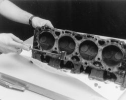
Fig. Fig. 1: Use a gasket scraper to remove the old gasket material from the mating surfaces
Most of the cleaning process can be carried out with common hand tools and readily available solvents or solutions. Carbon deposits can be chipped away using a hammer and a hard wooden chisel. Old gasket material and varnish or sludge can usually be removed using a scraper and/or cleaning solvent. Extremely stubborn deposits may require the use of a power drill with a wire brush. If using a wire brush, use extreme care around any critical machined surfaces (such as the gasket surfaces, bearing saddles, cylinder bores, etc.). Use of a wire brush is NOT RECOMMENDED on any aluminum components. Always follow any safety recommendations given by the manufacturer of the tool and/or solvent. You should always wear eye protection during any cleaning process involving scraping, chipping or spraying of solvents.
An alternative to the mess and hassle of cleaning the parts yourself is to drop them off at a local garage or machine shop. They will, more than likely, have the necessary equipment to properly clean all of the parts for a nominal fee.
| |
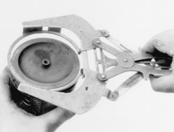
Fig. Fig. 2: Use a ring expander tool to remove the piston rings
Remove any oil galley plugs, freeze plugs and/or pressed-in bearings and carefully wash and degrease all of the engine components including the fasteners and bolts. Small parts such as the valves, springs, etc., should be placed in a metal basket and allowed to soak. Use pipe cleaner type brushes, and clean all passageways in the components. Use a ring expander and remove the rings from the pistons. Clean the piston ring grooves with a special tool or a piece of broken ring. Scrape the carbon off of the top of the piston. You should never use a wire brush on the pistons. After preparing all of the piston assemblies in this manner, wash and degrease them again.
| |
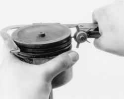
Fig. Fig. 3: Clean the piston ring grooves using a ring groove cleaner tool, or ...
| |
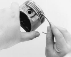
Fig. Fig. 4: ... use a piece of an old ring to clean the grooves. Be careful, the ring can be quite sharp
When cleaning the cylinder head, remove carbon from the combustion chamber with the valves installed. This will avoid damaging the valve seats.
REPAIRING DAMAGED THREADS
See Figures 5 through 9
| |
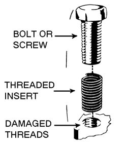
Fig. Fig. 5: Damaged bolt hole threads can be replaced with thread repair inserts

| |
Fig. Fig. 6: Standard thread repair insert (left), and spark plug thread insert
| |
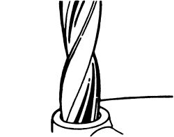
Fig. Fig. 7: Drill out the damaged threads with the specified size bit. Be sure to drill completely through the hole or to the bottom of a blind hole
| |
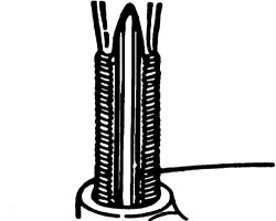
Fig. Fig. 8: Using the kit, tap the hole in order to receive the thread insert. Keep the tap well oiled and back it out frequently to avoid clogging the threads
| |
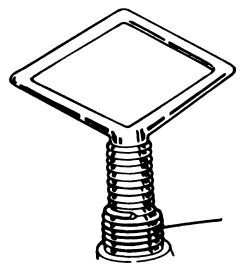
Fig. Fig. 9: Screw the insert onto the installer tool until the tang engages the slot. Thread the insert into the hole until it is 1/4-1/2 turn below the top surface, then remove the tool and break off the tang using a punch
Several methods of repairing damaged threads are available. Heli-Coil® (shown here), Keenserts® and Microdot® are among the most widely used. All involve basically the same principle-drilling out stripped threads, tapping the hole and installing a prewound insert-making welding, plugging and oversize fasteners unnecessary.
Two types of thread repair inserts are usually supplied: a standard type for most inch coarse, inch fine, metric course and metric fine thread sizes and a spark lug type to fit most spark plug port sizes. Consult the individual tool manufacturer's catalog to determine exact applications. Typical thread repair kits will contain a selection of prewound threaded inserts, a tap (corresponding to the outside diameter threads of the insert) and an installation tool. Spark plug inserts usually differ because they require a tap equipped with pilot threads and a combined reamer/tap section. Most manufacturers also supply blister-packed thread repair inserts separately in addition to a master kit containing a variety of taps and inserts plus installation tools.
Before attempting to repair a threaded hole, remove any snapped, broken or damaged bolts or studs. Penetrating oil can be used to free frozen threads. The offending item can usually be removed with locking pliers or using a screw/stud extractor. After the hole is clear, the thread can be repaired, as shown in the series of accompanying illustrations and in the kit manufacturer's instructions.