
REMOVAL & INSTALLATION
See Figures 1 through 14
The thermostat is installed on the inlet side of the water pump. Its purpose is to prevent overheating of the coolant by controlling the flow into the engine from the radiator. During warm up, the thermostat remains closed so that the coolant within the engine heats quickly and aids the warming up process.
As the coolant temperature increases, the thermostat gradually opens, allowing a supply of lower temperature coolant (from the radiator) to enter the water pump and circulate through the engine.
A thermostat should never be removed as a countermeasure to an overheating problem. The vehicle cooling system should be serviced, necessary components replaced, correct coolant added and cooling system pressurized.
 |  |
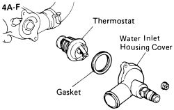
Fig. Fig. 1: Thermostat and gasket-4A-F engine
| |
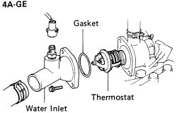
Fig. Fig. 2: Thermostat and gasket-4A-GE engine
| |
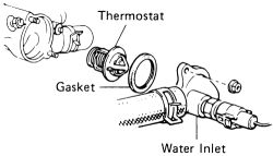
Fig. Fig. 3: Thermostat and gasket-4A-FE and 7A-FE engines
- Drain the cooling system and save the coolant for reuse.
| |
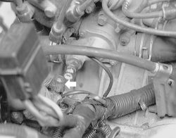
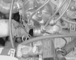
Fig. Fig. 4: Disconnect the sensor wiring from the thermostat housing
| |
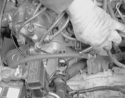
Fig. Fig. 5: Remove the hose from the housing
| |
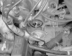
Fig. Fig. 6: Remove the bolts retaining the housing to the cylinder head ...
- Remove the water inlet (disconnect electrical wiring) and remove the thermostat. Carefully observe the positioning of the thermostat within the housing. Clean all mounting surfaces before installation.
| |
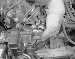
Fig. Fig. 7: ... then pull it from the cylinder head
| |
Fig. Fig. 8: Pull the thermostat and gasket out of the housing
| |
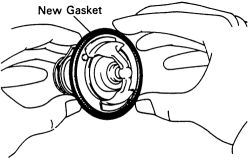
Fig. Fig. 9: Install a new gasket on the edge of the thermostat
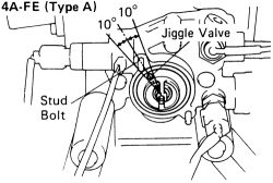
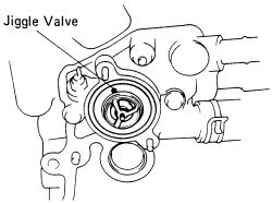
- On the 4A-FE engine, place the thermostat in the water inlet housing. Install a new gasket to the thermostat and align the jiggle valve of the thermostat as shown in the water inlet housing. The jiggle valve may be set within 10° of either side of the prescribed position (two types of thermostat are used).
| |
Fig. Fig. 10: Jiggle valve positioning-1988-92 4A-FE engine
| |
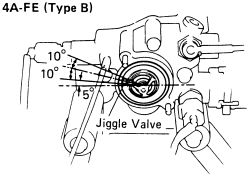
Fig. Fig. 11: Jiggle valve positioning-1988-92 4A-FE engine
| |
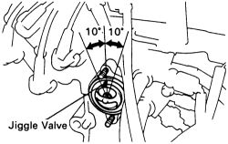
Fig. Fig. 12: Place the thermostat into the housing with the jiggle valve set in between these points-1993-97 4A-FE and 7A-FE engines
- On the 7A-FE engine, place the thermostat in the water inlet housing. Install a new gasket to the thermostat and align the jiggle valve of the thermostat with the upper side of the stud bolt. The jiggle valve may be set within 10° of either side of the prescribed position.
- On the 4A-F and 4A-GE engines, place the thermostat in the water inlet housing. Install a new gasket to the thermostat and align the jiggle valve of the thermostat so that it is positioned above the water inlet housing.
| |
Fig. Fig. 13: Align the jiggle valve to seat in this position-4A-F and 4A-GE engines
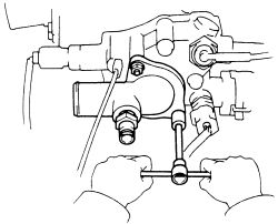
- Install the water inlet (attach electrical wiring). Install the two hold-down bolts or nuts and tighten them to 7 ft. lbs. (9 Nm) (in steps). Do not overtighten these bolts!
| |
Fig. Fig. 14: Tighten the two hold-down bolts or nuts in steps. Do not overtighten these bolts!
- Refill the cooling system with coolant.
- Start the engine. During the warm up period, observe the temperature gauge for normal behavior. Also during this period, check the water inlet housing area for any sign of leakage. Remember to check for leaks under both cold and hot conditions.