
REMOVAL & INSTALLATION 4F-E Engine
It is not necessary to remove the carburetor for this procedure. If you do, remember to inspect and replace any new hoses for gaskets.
- Relieve the fuel pressure. Disconnect the negative battery cable.
- Remove the air cleaner assembly. Drain the coolant.
- Tag and remove all wires, hoses or cables in the way of intake manifold removal. Remove the intake manifold stay (bracket).
See Figures 1, 2, 3 and 4
 |  |
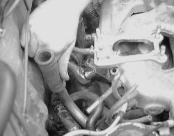
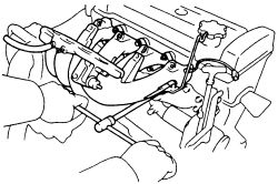
Fig. Fig. 1: Unbolt and remove the intake manifold stay located in the back of the engine
| |
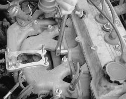
Fig. Fig. 2: Unbolt the intake manifold (carburetor removed) ...
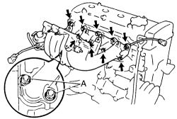
- Remove the seven bolts, two nuts, wire clamp, manifold and gasket from the engine. discard the old gasket.
| |
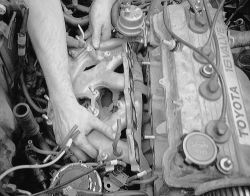
Fig. Fig. 3: ... then pull the manifold off the cylinder head
| |
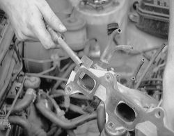
Fig. Fig. 4: Remember to scrape the gasket from the edge of the manifold and mating surface
- Install a new gasket and place the intake manifold into position. Attach the wire clamp, insert the seven bolts and two nuts. Tighten in steps to 14 ft. lbs. (19 Nm).
- Install the manifold stay and tighten the top bolt to 14 ft. lbs. (19 Nm) and the bottom bolt to 29 ft. lbs. (39 Nm). Check the vacuum diagram to attach any hoses not sure of during installation.
- Attach the water hose and connect the PCV hose. Reattach any wiring disconnected.
- Refill the cooling system with coolant.
- Start the engine. During the warm up period, observe the temperature gauge for normal behavior. Also during this period, check the water inlet housing area for any sign of leakage. Remember to check for leaks under both cold and hot conditions.
See Figures 5, 6, 7, 8 and 9
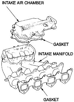
On the 1993-97 4A-FE and 7A-FE engines, the upper intake air chamber and intake manifold can be separated. A metal gasket is used to improve sealing performance. No cold start injector assembly is used on the 1993-97 vehicles.
- Relieve the fuel pressure. Disconnect the negative battery cable.
- Remove the air cleaner assembly. Drain the coolant.
- Tag and remove all wires, hoses or cables in the way of intake manifold removal. Remove the intake manifold stay (bracket).
| |
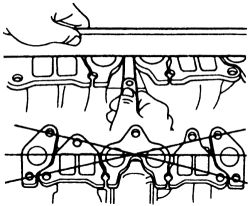
Fig. Fig. 5: Removing the intake manifold retaining bolts and nuts
- Remove the cold start injector pipe, if equipped.
| |
Fig. Fig. 6: View of the intake manifold and intake chamber-1993-97 4A-FE and 7A-FE engines
- Disconnect the electrical connectors and remove the fuel delivery pipe (fuel rail) and remove the injectors. During removal, be careful not to drop the injectors.
- Remove the intake manifold retaining bolts and nuts. Remove the intake manifold from the vehicle.
- On some models (usually 7A-FE) the EGR valve will be removed with the intake manifold. Separate the unit from the intake and attach to the new manifold.
- Clean the gasket mating surfaces, being careful not to damage them. Check the mating surfaces for warpage with a straightedge. The specification for maximum warpage on the intake manifold is on 4A-FE and 7A-FE engines: 0.0079 in. (0.20 mm) and on 4A-GE engines 0.0020 in. (0.05 mm). If warpage is greater than maximum, replace the manifold.
| |
Fig. Fig. 7: Measure the manifold for warpage
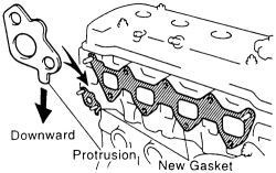
- On the 7A-FE engines if the EGR valve was removed, place a new gasket no the cylinder head facing the protrusion downward.
- Match the old gasket with the new one for an exact match. Use a new gasket when installing the manifold, then tighten the bolts and nuts evenly and in several passes from the center outward. Tighten the bolts to the following:
| |
Fig. Fig. 8: The 7A-FE engines utilize an EGR gasket, place into position correctly
- Intake manifold; 1988-89-20 ft. lbs. (27 Nm)
- Intake manifold; 1990-94-14 ft. lbs. (19 Nm)
- Intake manifold bolt (A) 1995-97-9 ft. lbs. (13 Nm)
- Intake manifold except (A) 1995-97-14 ft. lbs. (19 Nm)
-
Install the intake manifold stay (bracket) and tighten to specifications.
Intake manifold stay 1988-89-16 ft. lbs. (22 Nm)Intake manifold stay 12mm bolt 1990-97-14 ft. lbs. (19 Nm)Intake manifold stay 14mm bolt 1990-97-29 ft. lbs. (39 Nm)
| |
Fig. Fig. 9: Tighten the intake manifold bolts to specifications, (A) is a different specification
- Install the cold start injector pipe, if equipped. Tighten the cold start injector union bolt to 18 ft. lbs. (24 Nm).
- Install all necessary wires, hoses or cables. Install the air cleaner assembly.
- Refill the cooling system. Connect the negative battery cable. Start the engine. Check for leaks and road test for proper operation.