
REMOVAL & INSTALLATION 4A-GE Engine
See Figures 1 through 5
- Disconnect the negative battery cable. Raise the vehicle and support safely. Remove the right gravel shield from under the vehicle.
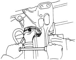
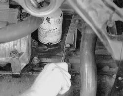
- Remove the front exhaust pipe from the exhaust manifold.
 |  |
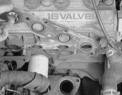
Fig. Fig. 1: Remove the three nuts retaining the front pipe to the exhaust manifold-4A-GE engine
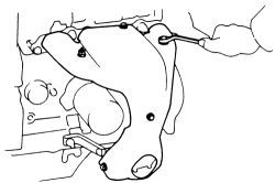
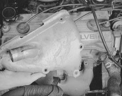
- Remove the four bolts and two nuts retaining the upper heat insulator. Pull the upper insulator off the vehicle.
| |
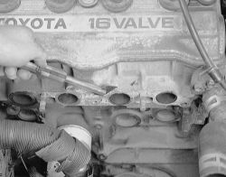
Fig. Fig. 2: Unbolt the upper insulator from the exhaust manifold-4A-GE engine
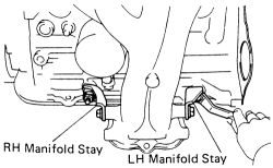
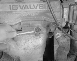
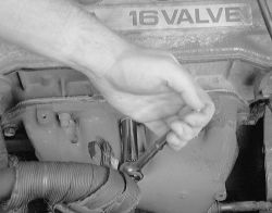
- Remove the three bolts retaining the left and right manifold stays.
| |
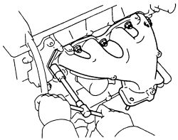
Fig. Fig. 3: Loosen and remove the manifold stay retaining bolts for both sides-4A-GE engine
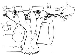
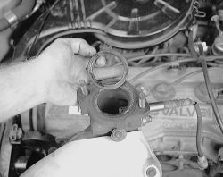
- Remove the manifold retaining nuts and bolts. Remove the exhaust manifold from the vehicle. discard the old gasket.
| |
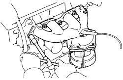
Fig. Fig. 4: Unbolt and separate the exhaust manifold from the engine-4A-GE engine
- Remove the bolts retaining the lower insulator to the manifold.
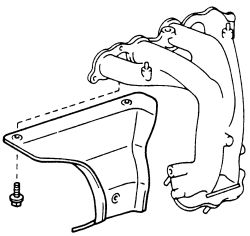
| |
Fig. Fig. 5: The lower insulator must be removed from the manifold also-4A-GE engine
- Clean the gasket mating surfaces, being careful not to damage them. Check the mating surfaces for warpage with a straightedge. The specification for maximum warpage on the exhaust manifold is 0.0118 in. (0.30 mm). If warpage is greater than maximum, replace the manifold.
- Attach the lower heat insulator to the exhaust manifold.
- Match the old gasket with the new one for an exact match. Use a new gasket when installing the manifold and tighten the bolts and nuts (in steps) from the center outward to 18 ft. lbs. (25 Nm).
- Install the remaining components and tighten left and right exhaust manifold stay bolts to 29 ft. lbs. (39 Nm).
- connect the front pipe to the exhaust manifold using new gaskets. Tighten the mounting nuts to 46 ft. lbs. (62 Nm).
- Start the engine and check for exhaust leaks.
- Disconnect the negative battery cable. Raise the vehicle and support safely. Remove the right gravel shield from under the vehicle.
- Separate the front exhaust pipe from the exhaust manifold.
- Remove the two bolts and manifold stay from the engine.
See Figures 6 through 14
| |
Fig. Fig. 6: Remove the two bolts retaining the manifold stay
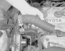
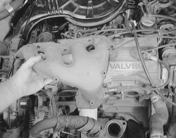
- Remove the air cleaner hose attached to the exhaust manifold.
| |
Fig. Fig. 7: Pull the hose from the exhaust manifold and air cleaner
- Remove the five bolts and the upper manifold insulator. Disconnect the oxygen sensor wiring. Unsecure the three bolts, two nuts and discard the gasket. Pull off the exhaust manifold. Remove the three bolts retaining the lower manifold insulator.
| |
Fig. Fig. 8: Loosen and remove the nuts and bolts retaining the upper insulator to the manifold-4A-F engine
| |
Fig. Fig. 9: Pull the upper heat shield off of the manifold and set it aside
| |
Fig. Fig. 10: Unbolt the manifold from the cylinder head
| |
Fig. Fig. 11: Lift the exhaust manifold off the engine
- Remove the oxygen sensor and install it into the new manifold. Always use a new gasket.
| |
Fig. Fig. 12: Discard the exhaust flange gasket ...
| |
Fig. Fig. 13: ... and the manifold gasket
| |
Fig. Fig. 14: Always clean the area of any gaket material
- Clean the gasket mating surfaces, being careful not to damage them. Check the mating surfaces for warpage with a straightedge. The specification for maximum warpage on the exhaust manifold is 0.0039 in. (0.10mm). If warpage is greater than maximum, replace the manifold.
- Install the lower manifold insulator with the three bolts. Using a new gasket, install the exhaust manifold with the two nuts and three bolts. Tighten the to 18 ft. lbs. (25 Nm).
- Install the upper manifold insulator with the five mounting bolts. Attach the manifold stay and tighten to 29 ft. lbs. (39 Nm).
- Attach the front pipe to the exhaust manifold using new gaskets, and tighten the nuts to 46 ft. lbs. (62 Nm).
- Install any other components removed. Attach the negative battery cable. Lower the vehicle to the ground and check for leaks.
- Attach the right gravel shield.
Only the 4A-FE engine was available on the 1988-92 models. Keep in mind that new nuts may be needed for the front exhaust pipe. Theses nuts are usually not reusable.
- Disconnect the negative battery cable. Raise the vehicle and support safely. Remove the right gravel shield from under the vehicle.
- Remove the front exhaust pipe from the exhaust manifold.
- Remove the upper heat insulator. Remove the manifold stay (bracket).
- Remove the manifold retaining nuts. Remove the exhaust manifold from the vehicle.
- Clean the gasket mating surfaces, being careful not to damage them. Check the mating surfaces for warpage with a straightedge. The specification for maximum warpage on the exhaust manifold is 0.0118 in. (0.30mm). If warpage is greater than maximum, replace the manifold.
- Match the old gasket with the new for an exact match. Use a new gasket when installing the manifold and tighten the bolts (in steps) from the center outward to 18 ft. lbs. (25 Nm).
- Install the remaining components and tighten the exhaust manifold stay (bracket) bolts to 29 ft. lbs. (39 Nm). Place new front pipe gaskets into position and tighten the pipe to the manifold to 46 ft. lbs. (62 Nm). New nuts may be needed during installation.
- Start the engine and check for exhaust leaks.
See Figures 15 and 16
On the 1993-97 models, the shape of the exhaust manifold was changed to adopt a manifold catalytic converter (TWC) on the California models. On these applications, remove the exhaust manifold assembly, then separate the catalytic converter from the manifold. Keep in mind that new nuts may be needed for the front exhaust pipe. Theses nuts are usually not reusable.
- Disconnect the negative battery cable. Raise the vehicle and support safely. Remove the right gravel shield from under the vehicle.
- On California models, separate the TWC from the front pipe. Removing the bolts and support bracket holding the front pipe to the TWC. Discard the front pipe exhaust gaskets.
- On all other models, remove the nuts securing the front exhaust pipe to the exhaust manifold. Discard the old exhaust pipe gaskets.
If the oxygen sensor must be removed on models equipped with them in the manifold, never reuse the old gasket. Replace the gasket.
| |
Fig. Fig. 15: Common non-California exhaust manifold-4A-FE and 7A-FE engines
| |
Fig. Fig. 16: Exhaust manifold with TWC catalyst attached-4A-FE and 7A-FE engines
-
To remove the exhaust manifold on all except California models:
- Remove the 5 bolts and upper heat insulator.
- Remove the 3 bolts and manifold stay.
- Remove the 5 nuts, exhaust manifold and gasket. Discard the old gasket.
- Remove the 3 bolts and lower heat insulator from the exhaust manifold.
-
To remove the exhaust manifold on California models:
- Disconnect the main oxygen sensor connection.
- Remove the 4 bolts securing the upper heat insulator.
- Remove the 2 bolts and manifold stay.
- Remove the 5 nuts, exhaust manifold assembly and gasket. Discard the old gasket.
- Remove the 3 bolts securing the lower heat insulator to the exhaust manifold.
- Clean the gasket mating surfaces, being careful not to damage them. Check the mating surfaces for warpage with a straightedge. The specification for maximum warpage on the exhaust manifold is 0.0039 in. (0.10mm). If warpage is greater than maximum, replace the manifold.
- Match the old gasket with the new for an exact match. Use a new gasket when installing the manifold.
If the oxygen sensor must be removed on models equipped with them in the manifold, never reuse the old gasket. Replace the gasket.
-
On California models:
- Install the lower heat insulator to the manifold with the 3 bolts.
- Install a new gasket and manifold with the 5 retaining nuts. Uniformly tighten the bolts in several passes to 25 ft. lbs. (34 Nm).
- Install the manifold stays with the 2 securing bolts. Alternately tighten the bolts to 29 ft. lbs. (39 Nm).
-
On non-California models:
- Install the lower insulator to the exhaust manifold with the 3 bolts.
- Install a new gasket and manifold with the 5 retaining nuts. Uniformly tighten the bolts in several passes to 25 ft. lbs. (34 Nm).
- Install the manifold stay with 3 bolts. Tighten the bolts alternately to 29 ft. lbs. (39 Nm).
- Install the upper heat shield and tighten the retaining bolts.
- Attach the front exhaust pipe to the manifold suing new gaskets. Tighten the securing nuts to 46 ft. lbs. (62 Nm). Install and tighten the bolts for the support bracket retaining the pipe to the TWC to 14 ft. lbs. (43 Nm). Connect the oxygen sensor wiring if equipped. Double check all components are secure.
- Connect the negative battery cable. Lower the vehicle. Start the engine and check for leaks. If non are found install the right gravel shield.
Install the remaining components and tighten the exhaust manifold stay (bracket) bolts to 29 ft. lbs. (39 Nm). Tighten the front exhaust pipe to the manifold to Start the engine and check for exhaust leaks.