
REMOVAL & INSTALLATION
See Figures 1 and 2
- Disconnect the negative battery cable. Drain the cooling system.
- Remove the coolant reservoir tank. Disconnect the upper radiator hose from the radiator.
 |  |
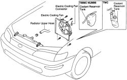
Fig. Fig. 1: View of the electric cooling fan components
- Disconnect the electric cooling fan connector. Remove the 4 bolts and remove the cooling fan and shroud as an assembly.
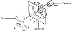
- Remove the cooling fan motor from the fan shroud, if necessary.
| |
Fig. Fig. 2: If necessary, separate the fan blade from the motor
- Reattach any components disassembled from the cooling fan assembly if separated. Tighten the cooling fan blade to 55 inch lbs. (6 Nm) and the fan motor to 23 inch lbs. (3 Nm).
- Secure the cooling fan assembly to the radiator.
- Attach the upper radiator hose.
- Connect the negative battery cable. Fill the cooling system. Start the engine and check for proper cooling fan operation. Top off the system as necessary.
TESTING
Always check all fuses and circuit breakers in all junction and relay blocks before troubleshooting the electric cooling fan circuit.
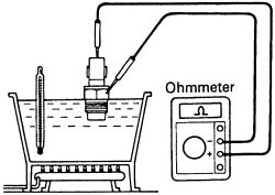
Engine Coolant Temperature (ECT) SwitchSee Figure 3
Inspect the vehicle with the coolant temperature is low, below 83° C (181° F).
- Turn the ignition ON. Check that the cooling fan stops. If not, check the cooling fan relay and electric coolant temperature switch (ECT), then check for a loose connection or severed wire between the cooling fan relay and ECT switch.
| |
Fig. Fig. 3: Check the temperature that the switch turns on
- Disconnect the ECT switch wiring. Check that the cooling fan rotates. If not, inspect the cooling fan relay, engine main relay and fuse. Check for a short circuit between the cooling fan relay and ECT switch. Attach the ECT switch wiring.
See Figures 4 and 5
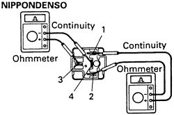
- Using an ohmmeter, check that there is continuity between terminal 1 and terminal 2.
| |
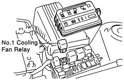
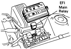
Fig. Fig. 4: The cooling fan relay is located in the fuse block in the engine compartment
| |
Fig. Fig. 5: Using an ohmmeter, check for continuity at the cooling fan relay
- Using an ohmmeter, check that there is continuity between terminal 3 and terminal 4.
- If continuity is not as specified, replace the relay.
See Figure 6
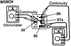
- Using an ohmmeter, check that there is continuity between terminals 86 and 85.
- Check that there is continuity between terminals 30 and 87a.
| |
Fig. Fig. 6: Using an ohmmeter, check for continuity at the terminals
- If continuity is not as specified, replace the relay.
See Figures 7 and 8
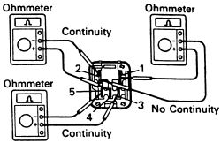
- Using an ohmmeter, check that there is continuity between terminal 1 and terminal 3.
- If continuity is not as specified, replace the relay.
| |
Fig. Fig. 7: The engine main relay is located in the fuse block in the engine compartment
| |
Fig. Fig. 8: Using an ohmmeter, check for continuity at the engine main relay
- Next, check that there is continuity between terminal 2 and terminal 4.
- If continuity is not as specified, replace the relay.
- Check that there is no continuity between terminal 3 and terminal 5.
- If continuity is not as specified, replace the relay.