
REMOVAL & INSTALLATION 4A-F and 4A-GE Engines
See Figures 1 through 9
- Disconnect the negative battery cable.
 |  |
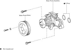
Fig. Fig. 1: View of the water pump and pulley-4A-F and 4A-GE engines
- Drain the engine coolant by opening the radiator and engine block draincocks.
- Raise and safely support the engine. Remove the front engine mounting insulator.
- On the 4A-GE engine, remove the power steering and A/C belts if equipped.
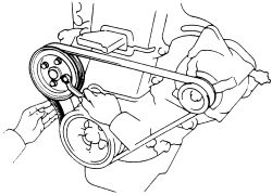
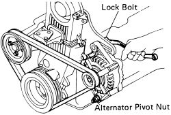
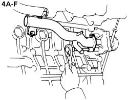
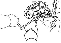
- Loosen the water pump pulley bolts. Loosen the alternator locking bolt and the pivot nut. Move the alternator till the belt is loose and remove the belt.
| |
Fig. Fig. 2: Loosening the water pump pulley bolts-4A-F and 4A-GE engines
| |
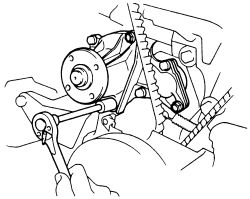
Fig. Fig. 3: Loosen the lockbolt and pivot nuts on the alternator-4A-F and 4A-GE engines
- Remove the four bolts on the water pump pulley and separate from the unit.
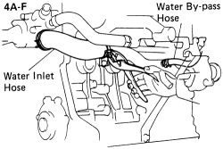
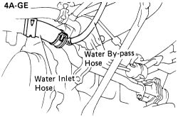
- Disconnect the water inlet and the bypass hoses from the inlet pipe.
| |
Fig. Fig. 4: Disconnect the water bypass and inlet hoses-4A-F engine
| |
Fig. Fig. 5: Disconnect the water bypass and inlet hoses-4A-GE engine
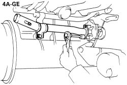
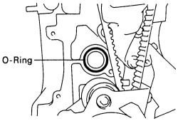
- Disconnect and remove the water inlet pipe by removing the two clamp bolts and the two nuts at the back of the pump. Remove the O-ring from the back of the pump.
| |
Fig. Fig. 6: Unbolt and remove the inlet pipe and O-ring-4A-F engine
| |
Fig. Fig. 7: Remove the two nuts retaining the inlet pipe-4A-GE engine
- Remove the mounting bolt for the dipstick tube; remove the tube and dipstick. Immediately plug the hole in block to prevent fluid from contaminating the oil.
| |
Fig. Fig. 8: Pull the oil dipstick tube out and plug the oil pump body hole
| |
Fig. Fig. 9: Unbolt and remove the waterpump
During the following steps, if coolant should get by the plug in the dipstick hole and run into the engine, the engine oil MUST be changed before starting the engine.
- Remove the No. 3 (upper) and No. 2 (middle) timing belt covers.
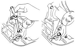
- Remove the water pump retaining bolts pull the unit off the front of the engine.
To install:
- Place the water pump gasket (O-ring) on the block and install the pump. Tighten the mounting bolts evenly to 11 ft. lbs. (15 Nm).
- Install the timing belt covers, making sure they are properly seated and not rubbing on the belt or other moving parts.
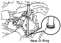
- Install a new seal (O-ring) on the dipstick tube and lightly coat it with engine oil. Remove the plug and install the dipstick tube and dipstick; secure the mounting bolt to 82 inch lbs. (9 Nm).
- Using a new O-ring, install the inlet pipe to the water pump.
- Attach the clamps and bolts to hold the pipe in place and tighten to 7-9 ft. lbs. (9-12 Nm).
- Connect the water inlet and water bypass hoses to the inlet pipe.
- Install the water pump pulley and temporarily tighten the four pulley bolts.
- Install the drive belts on all the pulleys and adjust all of them to the correct tension.
- With the belts in place and adjusted, the water pump pulley will now resist turning. Tighten the pulley bolts to 16-18 ft. lbs. (22-24 Nm).
- Install the front engine mount (mounting insulator).
- Confirm that the draincocks are closed on the engine block and radiator. Refill the engine with coolant. Reconnect the negative battery cable. Start the engine and check for leaks.
See Figures 10 through 16
- Disconnect the negative battery cable. Drain the engine coolant from the radiator.
- Remove all drive belts.
| |
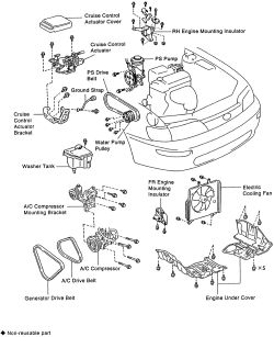
Fig. Fig. 10: Exploded view of the water pump removal components-4A-FE and 7A-FE engines
| |
Fig. Fig. 11: Exploded view of the water pump removal components (continued)-4A-FE and 7A-FE engines
- Support the engine using suitable equipment.
- Remove the right engine mount and insulator.

| |
Fig. Fig. 12: Unbolt and remove the right side engine insulator-4A-FE and 7A-FE engines
- Remove the No. 3 (upper) and No. 2 (middle) timing belt covers.
- If equipped with power steering, raise and safely support the vehicle. Remove the front transaxle mounting insulator. Access the nut and through-bolt, through the hole. Lower the vehicle, remove the cooling fan assembly.
| |
Fig. Fig. 13: Access hole to remove the nut and through-bolt for the front engine insulator-4A-FE and 7A-FE engines
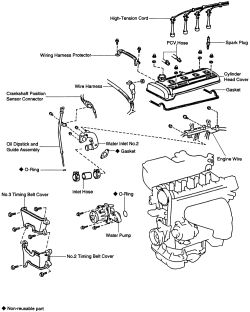
- Remove the mounting bolt for the dipstick tube; remove the tube and dipstick. Immediately plug the hole in the block to prevent fluid from contaminating the oil.
- If equipped, disconnect the crankshaft position sensor wiring from the dipstick guide. Remove the mounting bolt and pull out the dipstick guide and gauge. Discard the O-ring on the tube.
- Disconnect the wiring for the water temperature sensor.
- Remove the 2 nuts securing the engine coolant pipe to the cylinder block.
- Loosen the clamp and remove the coolant inlet pipe.
- Loosen the clamp and remove the coolant inlet hose from the water pump.
- If equipped with power steering, raise the engine and remove the mounting bolts for the water pump. Remove the water pump and O-ring from the vehicle.
| |
Fig. Fig. 14: Unbolt and remove the water pump and O-ring-4A-FE and 7A-FE engines
- Install a new O-ring to the vehicle. Install the water pump and tighten the retaining bolts evenly to 11 ft. lbs. (15 Nm).
| |
Fig. Fig. 15: Replace the O-ring on the block with a new one-4A-FE and 7A-FE engines
- Lower the engine if necessary, and connect the coolant hose to the water pump. Reconnect the engine coolant inlet pipe to the vehicle and secure to hose with clamp and secure to block with 2 nuts. Tighten the engine coolant inlet pipe nuts to 11 ft. lbs. (15 Nm).
- Connect the electrical wiring for the water temperature sensor.
- Place a new O-ring on the end of the dipstick tube. Install the oil guide tube and tighten the retaining bolt to 84 inch lbs. (9 Nm). Install the oil level indicator to the guide tube.
| |
Fig. Fig. 16: Don't forget to use a new O-ring on the tube before securing to the engine
- Attach the crankshaft position sensor wiring to the oil dipstick guide, if removed.
- Install the radiator fan assembly, if necessary.
- If equipped with power steering, raise and safely support the vehicle. Install the front transaxle mount. Tighten the through bolt nut to 64 ft. lbs. (87 Nm) and 2 mount bolts to 47 ft. lbs. (64 Nm). Install the hole cover.
- Lower the vehicle (if necessary) and install the No. 3 (upper) and No. 2 (middle) timing belt covers.
- Support the engine using suitable equipment. Install the right engine mount and insulator.
- Remove all engine lifting equipment.
- Install and adjust all drive belts.
- Reconnect the negative battery cable. Fill the cooling system. Start the engine and check for coolant leaks. Top off the system as necessary.