
SYSTEM OPERATION
See Figure 1
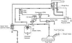
The Evaporative Emission Control (EVAP) system is designed to prevent fuel tank vapors from being emitted into the atmosphere. When the engine is not running, gasoline vapors from the tank are stored in a charcoal canister. The charcoal canister absorbs the gasoline vapors and stores them until certain engine conditions are met and the vapors can be purged and burned by the engine. In some vehicles, any liquid fuel entering the canister goes into a reservoir in the bottom of the canister to protect the integrity of the carbon element in the canister above. These systems employ the following components:
4A-F engine:4A-GE engine:
4A-FE and 7A-FE engines:
 |  |
Fig. Fig. 1: Evaporative Emission Control (EVAP) system components-4A-F engine shown, others similar
COMPONENT TESTING
See Figure 2
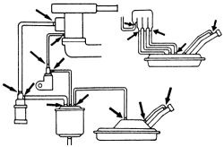
Before embarking on component removal or extensive diagnosis, perform a complete visual check of the system. Every vacuum line and vapor line (including the lines running to the tank) should be inspected for cracking, loose clamps, kinks and obstructions. Additionally, check the tank for any signs of deformation or crushing. Each vacuum port on the engine or manifold should be checked for restriction by dirt or sludge.
| |
Fig. Fig. 2: Always inspect the lines for kinks, cracks and loose connections
The evaporative control system is generally not prone to component failure in normal circumstances; most problems can be tracked to the causes listed above.
Fuel Filler CapSee Figure 3
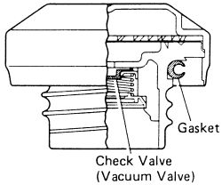
Check that the filler cap seals effectively. Replace the filler cap if the seal is defective.
| |
Fig. Fig. 3: Inspect the gasket on the fuel cap, if deteriorated, replace the gasket or cap as necessary
See Figures 4 and 5
- Remove the charcoal canister from the vehicle.
- Visually check the charcoal canister for cracks or damage.
| |
Fig. Fig. 4: Visually check the charcoal canister for cracks or damage
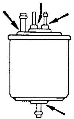
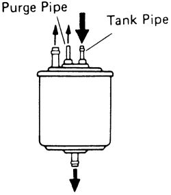
- Check for a clogged filter and stuck check valve. Using low pressure compressed air (0.68 psi. or 4 kPa), blow into the tank pipe and check that the air flows without resistance from the other pipes. If this does not test positive replace the canister.
| |
Fig. Fig. 5: To check for a clogged filter or check valve, blow compressed air into the pipes as shown
- Clean the filter in the canister by blowing no more than 43 psi (294 kPa) of compressed air into the pipe to the outer vent control valve while holding the other upper canister pipes closed.
Do not attempt to wash the charcoal canister. Also be sure that no activated carbon comes out of the canister during the cleaning process.
- Replace or reinstall the canister as needed.
See Figures 6 and 7
- Disconnect the hoses from the valve.
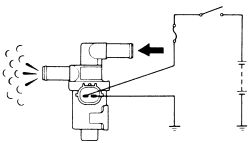
- Check that the valve opens when the ignition switch is OFF.
| |
Fig. Fig. 6: Check that the outer vent control opens when the ignition is OFF
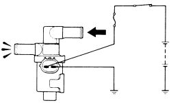
- Check that the valve is closed when the ignition switch is ON.
| |
Fig. Fig. 7: Check that the outer vent control closes when the ignition is ON
- Reattach the hoses to the proper locations. If the valve does not respond correctly to this test, replace the valve.
See Figure 8
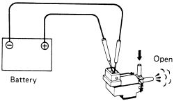
- Remove the VSV from the engine. Connect the VSV terminals to the battery terminals.
- Blow into the pipe of the valve, check that the VSV is open.
| |
Fig. Fig. 8: The VSV should be open when battery voltage is applied
- Disconnect the positive terminal of the battery.
- Blow into the pipe again and check that the valve is closed. If the testing is not found to be to standards, replace the valve.
- To test for a short in the valve; attach an ohmmeter, and check for continuity at the positive terminal and the body of the valve. If continuity is found, the valve is faulty.
- Testing the VSV for and open circuit. Using an ohmmeter, measure the resistance between the positive terminal and the other terminals. Resistance should be 38-44 ohms at 68° F (20° C)> If the resistance is not within specifications, replace the VSV.
- Remove the BVSV.
- Cool the BVSV to below 104° F (40° C) with cool water. Blow air into pipe and check that the BVSV is closed.
- Heat the BVSV to above 129° F (54° C) with hot water. Blow air into pipe and check that the BVSV is open. If a problem is found, replace the valve.
- Apply liquid sealer to the threads of the BVSV and reinstall.
See Figures 9 and 10
- Remove the TVV valve from the engine.
- Cool the valve to below 95° F (35° C) with cool water.
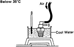
| |
Fig. Fig. 9: During the cold test, air should not flow from the upper port to the lower port of the TVV
- Make sure that air does not flow from the upper port to the lower port.
- Heat the TVV to above 129° F (54° C) with hot water.
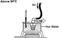
| |
Fig. Fig. 10: During the hot test, air should flow from the upper port to the lower port of the TVV
- Check that air flows from the upper port to the lower port of the valve. If the operation is not as specified, replace the TVV valve.
See Figures 11 and 12
- Drain the coolant from the radiator into a clean container.
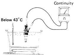
| |
Fig. Fig. 11: Cool the temperature switch and check for continuity
- Remove the thermo switch.
- Cool the switch off until the temperature is below 109°F (43°C). Check that there is continuity through the switch by the use of an ohmmeter.
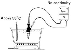
| |
Fig. Fig. 12: No continuity should be present when the temperature switch is heated
- Using hot water, bring the temperature of the switch to above 131°F (55°C). Check that there is no continuity when the switch is above this temperature.
- Apply sealer to the threads of the switch and reinstall it.
- Refill the radiator with coolant.
REMOVAL & INSTALLATION
When replacing any EVAP system hoses, always use hoses that are fuel-resistant or are marked EVAP. Use of hose which is not fuel-resistant will lead to premature hose failure.
Charcoal Canister- Label and disconnect the lines running to the canister. Remove the charcoal canister from the vehicle.
Do not attempt to wash the charcoal canister. Also be sure that no activated carbon comes out of the canister during the cleaning process.
- Attach the charcoal canister to its mounting bracket and secure. Connect the vacuum hoses in their proper locations.
- Drain the engine coolant from the radiator into a suitable container.
- Unscrew the BVSV from the engine.
- Apply liquid sealer to the threads of the BVSV. carefully thread the valve into the engine.
- Fill the radiator with coolant. Start the engine, check and top off the fluid level.
See Figure 13
- Drain the coolant the from the radiator.
- Disconnect the vacuum hoses from the charcoal canister (1) and throttle body (2).
- Remove the TVV valve from the engine.
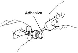
- Apply adhesive to 2 or 3 of the threads of the TVV, then tighten the valve to 22 ft. lbs. (29 Nm).
| |
Fig. Fig. 13: Apply adhesive to the first few threads of the valve prior to installation
- Reattach the vacuum hoses.
- Refill the engine with coolant. Start the engine, check and top off the fluid level.
- Disconnect and label the hoses from the valve.
- Remove the valve from its mounting bracket.
- Place a new valve into position on the bracket. Attach the hoses.