
This system is only used on 4A-F engines.
OPERATION
See Figure 1
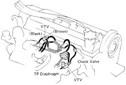
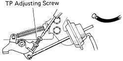
To reduce HC and CO emissions, the Throttle Positioner (TP) opens the throttle valve to slightly more than the idle position when decelerating. This keeps the air/fuel ratio from becoming excessively rich when the throttle valve is quickly closed. In addition, the TP is used to increase idle rpm when power steering fluid pressure exceeds a calibrated value and/or when a large electrical load is placed on the electrical system (headlights, rear defogger etc).
 |  |
Fig. Fig. 1: The Throttle Positioner (TP) system components
TESTING Vacuum Transmitting Valve (VTV)
See Figure 2
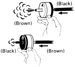
- Check that air flows without resistance from B to A.
| |
Fig. Fig. 2: Check the airflow from both sides of the VTV valve
- Check that air flows with difficulty from A to B.
- If a problem is found, replace the vacuum delay valve.
A should face the throttle positioner.
Vacuum Switching Valve (VSV)See Figures 3, 4 and 5
- Warm the engine to operating temperature.
- Check the idle speed and adjust if necessary.
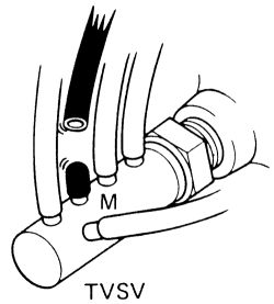
- Disconnect the hose from the TVSV M port and plug the port.
| |
Fig. Fig. 3: Disconnect the hose shown from the port and plug it
- Check the throttle positioner setting speed and operation of the VTV. Disconnect the vacuum hose from the TP diaphragm and plug the hose end.
| |
Fig. Fig. 4: Remove the hose from the TP diaphragm and plug the hose end
| |
Fig. Fig. 5: Turn the screw to adjust the TP setting speed if necessary
- Check that the TP is set to 900 rpm. If it is not at the specified speed, adjust with the TP adjusting screw. Make the adjustment with the cooling fan OFF.
- Reconnect the vacuum hose to the TP diaphragm and check that the engine returns to idle speed within 2-6 seconds. Reconnect the vacuum hose to the diaphragm.
- Reconnect the hose to the TVSV M port. If no problem is found with this inspection, the system is OK; otherwise inspect each part.
See Figure 6
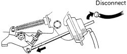
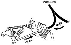
Check that the linkage moves in accordance with applied vacuum.
| |
Fig. Fig. 6: Check the linkage of the throttle position diaphragm for smooth movement