
SYSTEM OPERATION
The EGR system reduces oxides of nitrogen. This is accomplished by recirculating some of the exhaust gases through the EGR valve to the intake manifold, lowering peak combustion temperatures.
INSPECTION & TESTING 4A-F EngineSYSTEM CHECK
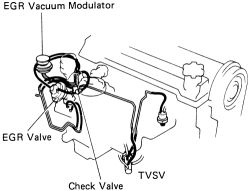
See Figure 1
 |  |
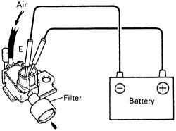
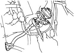
Fig. Fig. 1: Exhaust Gas Recirculation (EGR) system components-4A-F engine
- Check and clean the filter in the EGR vacuum modulator. Use compressed air (if possible) to blow the dirt out of the filters and check the filters for contamination or damage.
- Using a tee (3-way connector), connect a vacuum gauge to the hose between the EGR valve and the vacuum modulator.
- Check the seating of the EGR valve by starting the engine and seeing that it runs at a smooth idle. If the valve is not completely closed, the idle will be rough.
- With the engine coolant temperature below 122°F (50ºC), the vacuum gauge should read 0 at 2000 rpm. This indicates that the Thermal Vacuum Switching Valve (TVSV) is functioning correctly at this temperature range.
- Warm the engine to normal operating temperature. Check the vacuum gauge and confirm low vacuum at 2000 rpm. This indicates the TVSV and the EGR vacuum modulator are working correctly in this temperature range.
- Disconnect the vacuum hose from the R port on the EGR vacuum modulator and, using another piece of hose, connect the R port directly to the intake manifold. Check that the vacuum gauge indicates high vacuum at 2000 rpm.
Port R is the lower of the two ports. As a large amount of exhaust gas enters, the engine will misfire slightly at this time.
- Disconnect the vacuum gauge and reconnect the vacuum hoses to their proper locations.
- Check the EGR valve by applying vacuum directly to the valve with the engine at idle. (This may be accomplished either by bridging vacuum directly from the intake manifold or by using a hand-held vacuum pump.) The engine should falter and die as the full load of recirculated gasses enters the engine.
- If no problem is found with this inspection, the system is OK; otherwise inspect each part.
- Remove the EGR valve.
- Check the valve for sticking and heavy carbon deposits. If a problem is found, replace the valve.
- Reinstall the EGR valve with a new gasket.
- Label and disconnect the vacuum hoses from ports P, Q, and R of the EGR vacuum modulator.
Port P is the single port on the one side of the modulator. Port Q and R are stacked, with port Q being on top.
- Plug the P and R ports with your fingers.
- Blow air into port Q. Check that the air passes freely through the sides of the air filter.
- Start the engine and maintain 2000 rpm.
- Repeat the test above. Check that there is a strong resistance to air flow.
- Reconnect the vacuum hoses to the proper locations.
See Figure 2
- Drain the coolant from the radiator into a suitable container.
- Remove the TVSV from the engine.
- Plac the TVSV into cool water below 45° F (7°C).
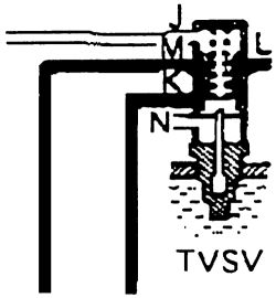
- See if air flows from pipe J to pipes M and L, and flows from pipe K to pipe N.
| |
Fig. Fig. 2: TVSV port identification
- Place the TVSV into hot water at 63-122° F (17-50° C).
- See if air flows from pipe K to pipes N and L, and flows from pipe J to pipe M.
- Heat the TVSV to above 154° F (68° C).
- See if air flows from pipe K to pipes M and L, and does not flow from pipe J to the other pipes.
- Apply liquid sealer to the first few threads of the TVSV and reinstall it in the engine.
- Fill the radiator with the correct coolant water mixture. Start the vehicle and check for leaks, top off if necessary.
If a problem was found during testing, replace the TVSV.
4A-GE EngineSYSTEM CHECK-1988-89 MODELSSee Figure 3
| |
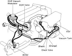
Fig. Fig. 3: Exhaust Gas Recirculation (EGR) system components-1988-89 4A-GE engines
- Check and clean the filter in the EGR vacuum modulator. Use compressed air (if possible) to blow the dirt out of the filters and check the filters for contamination or damage.
- Using a tee (3-way connector), connect a vacuum gauge to the hose between the EGR valve and the vacuum modulator.
- Check the seating of the EGR valve by starting the engine and seeing that it runs at a smooth idle. If the valve is not completely closed, the idle will be rough.
- With the engine coolant temperature below 95°F (35°C), the vacuum gauge should read 0 at 3500 rpm. This indicates that the Bimetal Vacuum Switching Valve (BVSV) is functioning correctly at this temperature range.
- Warm the engine to normal operating temperature. Check the vacuum gauge and confirm low vacuum at 3500 rpm. Check that the vacuum gauge is at 5000 rpm at zero. This indicates the BVSV, VSV and the EGR vacuum modulator are working correctly in this temperature range.
- Disconnect the vacuum hose from the R port on the EGR vacuum modulator and, using another piece of hose, connect the R port directly to the intake manifold. Check that the vacuum gauge indicates high vacuum at 3500 rpm.
Port R is the lower of the two ports. As a large amount of exhaust gas enters, the engine will misfire slightly at this time.
- Disconnect the vacuum gauge and reconnect the vacuum hoses to their proper locations.
- Check the EGR valve by applying vacuum directly to the valve with the engine at idle. (This may be accomplished either by bridging vacuum directly from the intake manifold or by using a hand-held vacuum pump.) The engine should falter and die as the full load of recirculated gasses enters the engine.
- If no problem is found with this inspection, the system is OK; otherwise inspect each part.
See Figures 4 and 5
| |
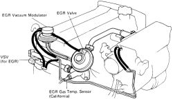
Fig. Fig. 4: Exhaust Gas Recirculation (EGR) system components-1990-91 4A-GE engines
- Check and clean the filter in the EGR vacuum modulator. Use compressed air (if possible) to blow the dirt out of the filters and check the filters for contamination or damage.
- Using a tee (3-way connector), connect a vacuum gauge to the hose between the EGR valve and the vacuum modulator.
- Check the seating of the EGR valve by starting the engine and seeing that it runs at a smooth idle. If the valve is not completely closed, the idle will be rough.
- With the engine coolant temperature below 129°F (54°C), the vacuum gauge should read 0 at 2500 rpm. This indicates that the Vacuum Switching Valve (VSV) is functioning correctly at this temperature range.
- Warm the engine to normal operating temperature. Check the vacuum gauge and confirm low vacuum at 3500 rpm. This indicates the VSV and the EGR vacuum modulator are working correctly in this temperature range.
- Disconnect the vacuum hose from the R port on the EGR vacuum modulator and, using another piece of hose, connect the R port directly to the intake manifold. Check that the vacuum gauge indicates high vacuum at 2500 rpm.
Port R is the lower of the two ports. As a large amount of exhaust gas enters, the engine will misfire slightly at this time.
- Disconnect the vacuum gauge and reconnect the vacuum hoses to their proper locations.
- Check the EGR valve by applying vacuum directly to the valve with the engine at idle. (This may be accomplished either by bridging vacuum directly from the intake manifold or by using a hand-held vacuum pump.) The engine should falter and die as the full load of recirculated gasses enters the engine.
- If no problem is found with this inspection, the system is OK; otherwise inspect each part.
- Remove the EGR valve.
- Check the valve for sticking and heavy carbon deposits. If a problem is found, replace the valve.
- Reinstall the EGR valve with a new gasket.
- Label and disconnect the vacuum hoses from ports P, Q, and R of the EGR vacuum modulator.
- Plug the P and R ports with your fingers.
- Blow air into port Q. Check that the air passes freely through the sides of the air filter.
Port P is the single port on the one side of the modulator. Port Q and R are stacked, with port Q being on top.
- Start the engine and maintain 3500 rpm on 1988-89 models; and 2500 rpm on 1990-91 models.
- Repeat the test above. Check that there is a strong resistance to air flow.
- Reconnect the vacuum hoses to the proper locations.
See Figure 5
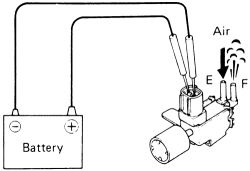
- Connect the vacuum switching valve terminals to the battery.
- Blow air into pipe E and check that the air comes out of pipe F.
- Disconnect the battery terminals.
- Blow air into pipe E and check that air comes out of air filter. If a problem is found, replace the VSV.
| |
Fig. Fig. 5: With battery voltage applied, air should pass through the pipes
- Check for a short circuit within the valve. Using an ohmmeter, check that there is no continuity between the terminal and the VSV body. If there is continuity, replace the VSV.
- Check for an open circuit. Using an ohmmeter, measure the resistance (ohms) between the two terminals of the valve. The resistance should be 33-39 ohms at 68°F (20°C). If the resistance is not within specifications, replace the VSV.
The resistance will vary slightly with temperature. It will decrease in cooler temperatures and increase with heat. Slight variations due to temperature range are not necessarily a sign of a failed valve.
BI-METAL VACUUM SWITCHING VALVE (BVSV)-1988-89 MODELS- Drain the coolant from the radiator into a suitable container.
- Remove the BVSV.
- Cool the BVSV in water below 95°F (35° C).
- Blow air into a pipe and check that the BVSV is closed.
- Heat the valve in water above 129° F (54° C).
- Blow air into the pipe and check that the valve is open.
- Apply liquid sealer to the first few threads of the valve and reinstall it in the engine.
- Fill the radiator with coolant and water mixture. Start the engine and check for leaks.
- If a problem is found with the testing of the BVSV, replace the valve.
See Figure 6
The EGR system is used on all 1988-92 models. From 1993-94 only California models were equipped with EGR. In 1995 only the 7A-FE engine was equipped with EGR. On 1996-97 models, both the 4A-FE and 7A-FE engines had EGR.
- Check and clean the filter in the EGR vacuum modulator. Use compressed air (if possible) to blow the dirt out of the filters and check the filters for contamination or damage.
- Using a tee (3-way connector), connect a vacuum gauge to the hose between the EGR valve and the vacuum modulator.
- Check the seating of the EGR valve by starting the engine and seeing that it runs at a smooth idle. If the valve is not completely closed, the idle will be rough.
- With the engine coolant temperature below 117°F (47°C), the vacuum gauge should read 0 at 2500 rpm.
The check connector is located near the air cleaner.
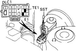
- On 1988-94 models perform the following:
| |
Fig. Fig. 6: Connect terminals TE1 and E1 in the data link connector
-
On 1995-97 models perform the following:
- Warm the engine up above 127°F (53°C). check that the vacuum gauge indicates low vacuum at 2500 rpm.
- Disconnect the hose from port R of the EGR vacuum modulator and connect port R directly to the intake manifold with another hose. Check the vacuum and make sure the reading is high at 2500 rpm.
Port R is the lower of the two ports. As a large amount of exhaust gas enters, the engine will misfire slightly at this time.
- Disconnect the vacuum gauge, SST or jumper wire and reconnect the vacuum hoses to their proper locations.
- Check the EGR valve by applying vacuum directly to the valve with the engine at idle. (This may be accomplished either by bridging vacuum directly from the intake manifold or by using a hand-held vacuum pump.) The engine should falter and die as the full load of recirculated gasses enters the engine.
- Remove the jumper from the check connector.
- If no problem is found with this inspection, the system is OK; otherwise inspect each part.
- Remove the EGR valve.
- Check the valve for sticking and heavy carbon deposits. If a problem is found, replace the valve.
- Reinstall the EGR valve with a new gasket.
See Figures 7 and 8
- Label and disconnect the vacuum hoses from ports P, Q, and R of the EGR vacuum modulator.
- Plug the P and R ports with your fingers.
| |
Fig. Fig. 7: Blow air into port Q and check that the air passes freely through filter of the vacuum modulator
- Blow air into port Q. Check that the air passes freely through the sides of the air filter.
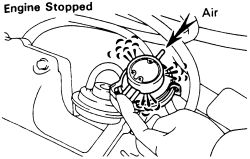
- Start the engine and maintain 2500 rpm.

| |
Fig. Fig. 8: Repeat the test with the engine running at 2500 rpm. Air should not pass through the filter
- Repeat the test above. Check that there is a strong resistance to air flow.
- Reconnect the vacuum hoses to the proper locations.
See Figures 9 and 10
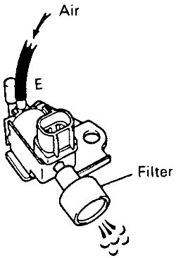
- Check that air flows from port E to the filter.
| |
Fig. Fig. 9: Check that air flows from port E to the filter of the VSV
- Connect the vacuum switching valve terminals to the battery.
| |
Fig. Fig. 10: Apply battery voltage across the terminals of the VSV
- Check that air flows from port E to port F.
- If the VSV fails this test replace it. Any doubts perform the following test.
- Remove the VSV.
- Check for a short circuit within the valve. Using an ohmmeter, check that there is no continuity between the terminals and the VSV body. If there is continuity, replace the VSV.
- Check for an open circuit. Using an ohmmeter, measure the resistance (ohms) between the two terminals of the valve. The resistance (cold) should be 37-44 ohms. If the resistance is not within specifications, replace the VSV.
REMOVAL & INSTALLATION EGR Valve
See Figures 11, 12, 13, and 14
On some models the EGR valve can be unbolted, hoses labeled and removed from the vehicle. On other models the following procedure will be required.
| |
Fig. Fig. 11: When removing the EGR valve, label and disconnect the vacuum hoses
| |
Fig. Fig. 12: Remove the EGR retaining nuts ...
| |
Fig. Fig. 13: ... then lift the valve off the intake manifold
- Disconnect the negative battery cable.
- Remove the air cleaner hose and lid. Disconnect the IAT sensor wiring.
- Disconnect the accelerator cable bracket from the throttle body.
- Remove the throttle body from the air intake chamber.
- Unbolt and remove the engine hanger, air intake chamber stay and EGR vacuum modulator. Discard the vacuum modulator gasket.
- Loosen the union nut of the EGR valve. Disconnect and label the hoses attached to the valve.
- Disconnect the EGR gas temperature sensor wiring.
| |
Fig. Fig. 14: On some engines, you must loosen the union from the EGR valve pipe
- Remove the nuts, EGR valve and pipe. Discard the gaskets.
- Place a new gasket on the cylinder head facing the protrusion downward. Install another gasket on the EGR valve and pipe and secure with the mounting nuts. Tighten them to 9 ft. lbs. (13 Nm).
- Connect the EGR gas temperature sensor wiring.
- Attach the vacuum hoses to the valve in their proper locations.
- Tighten the union nut on the EGR valve to 43 ft. lbs. (59 Nm).
- Install the air intake chamber stay, vacuum modulator and engine hanger. Place a new gasket into position facing the protrusion downward. Tighten the assembly down with the bolt and nut to 21 ft. lbs. (28 Nm). Attach the hoses.
- Install the throttle body with a new gasket. Tighten the bolts and nuts to 16 ft. lbs. (22 Nm). Attach all wiring and hoses removed.
- Connect the accelerator cable bracket to the throttle body, tightening the bolts to 8 ft. lbs. (11 Nm).
- Install the air cleaner and hose. Attach the IAT sensor connection.
- Attach the negative battery cable.