
OPERATION
See Figure 1
This system only applies to the 4A-F engine.
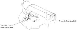
This system cuts off part of the fuel in the slow circuit of the carburetor to prevent overheating and afterburning of the exhaust system.
 |  |
Fig. Fig. 1: Deceleration fuel cut system components
TESTING
See Figures 2 and 3
- Connect a tachometer to the engine.
- Start the engine and check that it runs normally.
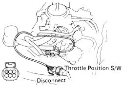
- Disconnect the throttle position switch terminal.
| |
Fig. Fig. 2: Disconnect the throttle position switch wire from the harness
- Gradually increase the engine speed to 2300 rpm. Check that the engine slightly fluctuates.
WARNING
Perform this procedure quickly to avoid overheating the catalytic converter.
- Reconnect the throttle position switch terminal. Again gradually increase the engine speed to 2300 rpm. and check that the engine operation is normal.
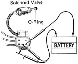
- With the engine at idle unplug the solenoid valve. Connect two terminals and the battery terminals as shown.
| |
Fig. Fig. 3: Connect the two terminals of the solenoid to the battery
- Check for a click in the solenoid valve when the battery is connected and disconnected.
- Check the O-ring for damages.
- Reinstall the valves and reattach the wiring.
REMOVAL & INSTALLATION Fuel Cut Solenoid Valve
This solenoid valve is only applicable to the 4A-F carbureted engines.
- Disconnect the solenoid valve wiring.
- Carefully unscrew the valve from the carburetor. Discard the old O-ring.
- Place a new O-ring on the end of the valve and securely tighten the unit into the carburetor.