
TESTING
See Figures 1 and 2
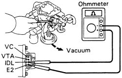
- Apply vacuum to the throttle opener.
- Insert a feeler gauge between the throttle stop screw and stop lever.
- Using an ohmmeter, measure the resistance between each terminal.
 |  |
Fig. Fig. 1: Check for resistance between these two terminals of the throttle position sensor
-
If necessary, adjust the TP sensor.
- Apply vacuum to the throttle opener. Insert a 0.028 inch (0.70mm) feeler gauge between the throttle stop screw and stop lever.
- Connect the test probe of an ohmmeter to the terminals IDL and E2 of the TP sensor.
- Gradually turn the TP sensor clockwise until the ohmmeter deflects, and secure it with the set screws.
- Recheck the continuity between terminals IDL and E2.
| |
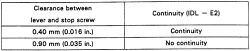
Fig. Fig. 2: Throttle position sensor continuity chart