
1989-95 MODELS
- Make sure the battery voltage is at least 11 volts.
- Make sure the throttle valve is fully closed.
- Place the gear shift lever in Neutral. Turn all accessories off.
- The engine should be at normal operating temperature.
- Using a jumper wire, connect terminals TE1 and E1 of the Data Link Connector 1 (DLC1).
- Turn the ignition switch ON, but do not start the engine. Read the diagnostic code by the counting the number of flashes of the malfunction indicator lamp.
- Codes will flash in numerical order. If no faults are stored, the lamp flashes continuously every 1/2 second. This is sometimes called the Normal or System Clear signal.
- After the diagnosis check, turn the ignition OFF and remove the jumper wire.
- Compare the codes found to the applicable diagnostic code chart. If necessary, refer to the individual component tests in this section. If the component tests are OK, test the wire harness and connectors for shorts, opens and poor connections.
1996-97 MODELS
These models require the use of the Toyota's hand held scan tool or an equivalent OBD II compliant scan tool.
- Prepare the scan tool according to the manufacturers instructions.
- Connect the OBD II scan tool, to the DLC3 under the instrument panel.
 |  |
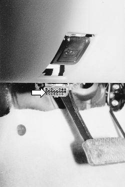
Fig. Fig. 1: The DLC3 on the 1996-97 models is located on the drivers side under the dash
When the diagnosis system is switched from the normal mode to the check mode, it erases all Diagnostic Trouble Codes (DTC) and freeze frame data recorded. Before switching modes, always check the DTC and freeze frame data and write them down.
- Turn the ignition switch to the ON and switch the OBD II scan tool switch on.
- Use the OBD II scan tool to check the DTC and freeze frame data. Write them down.
- Compare the codes found to the applicable diagnostic code chart. If necessary, refer to the individual component tests in this section. If the component tests are OK, test the wire harness and connectors for shorts, opens and poor connections.