
REMOVAL & INSTALLATION
See Figures 1 through 7
- Loosen the wheel nuts and the center axle nut.
- Raise the vehicle and safely support it.
 |  |
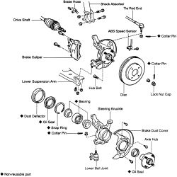
Fig. Fig. 1: Exploded view of the front axle hub and knuckle components
- Remove the wheel. Remove the ABS speed sensor if so equipped.
- Unclamp the brake hose from the shock absorber, but do not disconnect the line.
- Remove the brake caliper and hang it out of the way on a piece of stiff wire. Do not disconnect the brake line; do not allow the caliper to hang by the hose.
- Remove the brake disc.
| |
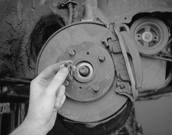
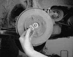
Fig. Fig. 2: Pull off the nut and washer holding the rotor to the shaft
-
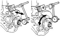
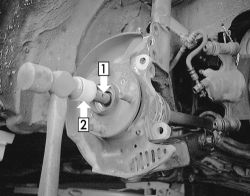
Place a dial indicator near the center of the axle hub, and check the backlash in the bearing shaft direction. Maximum is 0.0020 inch (0.05mm). If the backlash exceeds the maximum, replace the bearing.
- Usiung a dial; indicator, check the deviation at the surface of the axle hub outside the hub bolt. Maximum is 0.0028 inch (0.07mm). If the deviation exceeds the maximum, replace the axle hub.
- Install the disc and caliper. Tighten to 65 ft. lbs. (88 Nm).
| |
Fig. Fig. 3: Check the bearing backlash and axle hub deviation
- Remove the cotter pin and install the wheel. Lower the vehicle to the ground.
- Remove the lock nut cap. While depressing the brake pedal, remove the center axle nut.
| |
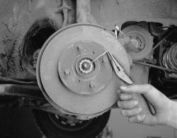
Fig. Fig. 4: Remove the cotter pin from the front hub
| |
Fig. Fig. 5: Remove the castleated nut
- Raise and support the vehicle again and remove the wheel, caliper and disc.
- Loosen the 2 nuts on the lower side of the shock absorber. Do not remove the 2 nuts and bolts.
- Remove the cotter pin and nut from the tie rod end.
- Remove the tie rod end from the knuckle using a joint separator or equivalent.
- Remove the bolt and 2 nuts holding the bottom of the ball joint to the control arm and separate the arm from the knuckle.
- Remove the 2 nuts from the steering knuckle. Place a protective cover or shield over the CV boot on the driveshaft.
| |
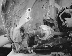
Fig. Fig. 6: Gently tap the end of the driveshaft to allow the hub and knuckle to come off
- Using a plastic mallet, tap the driveshaft free of the hub assembly.
- Remove the bolts and remove the axle hub assembly.
| |
Fig. Fig. 7: Remove the hub and knuckle as an assembly
- Clamp the knuckle in a vise with protected jaws.
- Remove the dust deflector. Loosen the nut holding the ball joint to the knuckle. Use a ball joint separator tool or equivalent to loosen and remove the joint
- Use a slide hammer/extractor to remove the outer oil seal.
- Remove the snapring.
- Using a hub puller and pilot tools or equivalents, pull the axle hub from the knuckle.
- Remove the brake splash shield (3 bolts).
- Use a split plate bearing remover, puller pilot and a shop press, remove the inner bearing race from the hub.
- Remove the inner oil seal with the same tools used to remove the outer seal.
- Place the inner race in the bearing. Support the knuckle and use an axle hub remover with a plastic mallet to drive out the bearing.
- Clean and inspect all parts but do not wash or clean the wheel bearing; it cannot be repacked. If the bearing is damaged or noisy, it must be replaced.
- Press a new bearing race into the steering knuckle using a bearing driver of the correct size.
- Place a new bearing inner race on the hub bearing.
- Insert the side lip of a new oil seal into the seal installer and drive the oil seal into the steering knuckle.
- Apply multi-purpose grease to the oil seal lip.
- Apply sealer to the brake splash shield and install the shield.
- Use a hub installer to press the hub into the steering knuckle.
- Install a new snapring into the hub.
- Using a seal installer of the correct size, install a new outer oil seal into the steering knuckle.
- Apply multi-purpose grease to the seal surfaces which will contact the driveshaft.
- Support the knuckle and drive in a new dust deflector.
- Install the ball joint into the knuckle and tighten the nut to 105 ft. lbs. (142). Install NEW cotter pin.
- Temporarily install the hub assembly to the lower control arm and fit the driveaxle into the hub.
- Install the knuckle to strut bolts, then attach the tie rod end to the knuckle.
- Tighten the strut bracket nuts to 203 ft. lbs. (275 Nm) and tighten the tie rod end nut to 36 ft. lbs. (49 Nm). Install the NEW cotter pin.
- Connect the ball joint to the lower control arm and tighten the nuts to 105 ft. lbs. (142 Nm).
- Install the brake disc.
- Attach the brake caliper to the knuckle and tighten the bolts to 65 ft. lbs. (88 Nm).
- Install the center nut and washer on the drive axle.
- Install the ABS speed sensor if so equipped. Install the wheel
- Lower the car to the ground.
- Tighten the wheel nuts to 76 ft. lbs. (103 Nm). Tighten the hub nut while depressing the brake pedal to 137 ft. lbs. (186 Nm) on 1988-91 models and 152 ft. lbs. (206 Nm) on 1992-97 models. Install the cap and cotter pin.
- Remove the protective cover from the CV boot. Check front wheel alignment.