
REMOVAL & INSTALLATION
See Figure 1
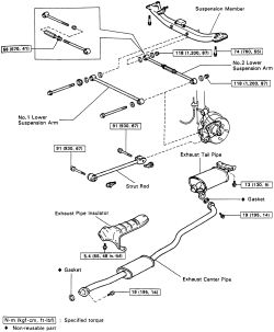
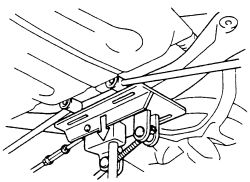
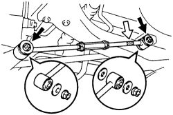
These vehicles use two control arms on each rear wheel. To avoid the obvious confusion they are referred to as No. 1 and No. 2, with arm No.1 being the closest to the front of the car. The strut rod is the bar going from front to rear of the vehicle.
 |  |
Fig. Fig. 1: Exploded view of the 2WD rear suspension components-1988-92 models
See Figures 2 through 6
Always matchmark all components prior to removal.
- Raise and safely support the vehicle.
- If necessary, remove the exhaust system.
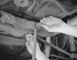
- Disconnect the strut rod.
- Remove the No. 2 lower suspension arm.
| |
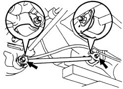
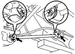
Fig. Fig. 2: Remove the No. 2 arm retaining nuts and lower the arm from the car
- Support the rear crossmember with a jack. Remove the bolts retaining the crossmember and lower.
| |
Fig. Fig. 3: Support the rear crossmember with a jack
| |
Fig. Fig. 4: Unbolt the rear crossmember ...
| |
Fig. Fig. 5: ... then lower the crossmember with the jack
- Remove the bolt and washer, then disconnect the No. 1 arm from the axle carrier.
- Lower the crossmember, remove the bolt, washer and No.1 arm.
| |
Fig. Fig. 6: Remove the No. 1 arm from the crossmember
- Install the No. 1 arm with the washers and bolts. Face the paint mark to the inside.
- Attach the rear crossmember, tighten the retaining bolts to 55 ft. lbs. (74 Nm).
- Install the exhaust system. Always replace the gaskets prior to installation.
- Install the No. 2 arm, hand tighten the two lock nuts.
- Install the strut rod and hand tighten the nuts till later.
- Install the rear wheels. Lower the vehicle.
- Bounce the car up and down several times to stabilize the suspension.
- Jack up the vehicle again and support the body with stands.
- Remove the rear wheel. Support the rear axle carrier with a jack.
Tighten the nuts of the No. 2 arm to 87 ft. lbs. (118 Nm) and the strut rod bolt to 67 ft. lbs. (91 Nm).
- Install the rear wheels and lower the vehicle.
- Inspect and adjust the rear wheel alignment.
- Tighten the No. 2 arm lock nuts to 41 ft. lbs. (56 Nm).
See Figures 7 through 13
Always matchmark all components prior to removal.
- Raise and safely support the vehicle.
- Observe and matchmark the position of the adjusting cam at the body mount.
- Remove the cover under the rear crossmember as shown in the illustration to access the rear arm mounting.
- Disconnect the bolt holding the arm to the suspension knuckle.
- Disconnect the bolt holding the arm to the body.
- Remove the arm.
| |
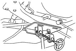
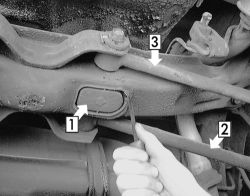
Fig. Fig. 7: No. 2 arm mounting access cover
| |
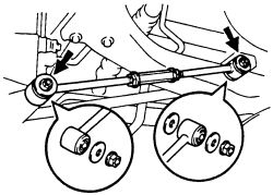
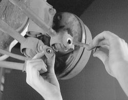
Fig. Fig. 8: While retaining the nut from the inside, remove the bolt on the outside
| |
Fig. Fig. 9: Once removed, be sure not to loose the adjusting cam
| |
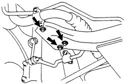
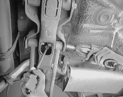
Fig. Fig. 10: Remove the arm mounting bolt from the other side
| |
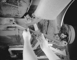
Fig. Fig. 11: Pull the arm from the under the vehicle
- Inspect the arms for any bending or cracking. If the arm is not true in all dimensions, it must be replaced. Any attempt to straighten a bent arm will damage it. Also check the bushings within the ends of the arms and replace any which are deformed or too spongy. If a bushing must be replaced, do not grease it before installation.
- When installing the No. 2 arm, place the washers and hand tighten the nuts.
- Install the strut rod and hand tighten the nuts till later.
| |
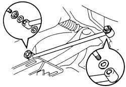
Fig. Fig. 12: Place the washers and nuts on the No. 2 arm in this order
| |
Fig. Fig. 13: Attach the strut rod and hand-tighten the nuts
- Install the rear wheels. Lower the vehicle.
- Bounce the car up and down several times to stabilize the suspension.
- Jack up the vehicle again and support the body with stands.
- Remove the rear wheel. Support the rear axle carrier with a jack.
Tighten the nuts of the No. 2 arm to 87 ft. lbs. (118 Nm) and the strut rod bolt to 67 ft. lbs. (91 Nm).
- Install the rear wheels and lower the vehicle.
- Inspect and adjust the rear wheel alignment.
- Tighten the No. 2 arm lock nuts to 41 ft. lbs. (56 Nm).
See Figure 14
Always matchmark all components prior to removal.
- Loosen the lug nuts and raise and support the vehicle.
- Remove the rear wheel.
- On some models it may be necessary to remove the exhaust system.
- Remove the 2 bolts, nuts and strut rod.
| |
Fig. Fig. 14: Remove the bolts and nuts retaining the strut rod to the vehicle
- Attach the strut rod and hand tighten the nuts.
- Install the exhaust system if removed.
- Install the rear wheels and lower the vehicle.
- Tighten the lugs nuts to 76 ft. lbs. (103 Nm).
- Inspect and adjust the rear wheel alignment.