
REMOVAL & INSTALLATION 2WD Models
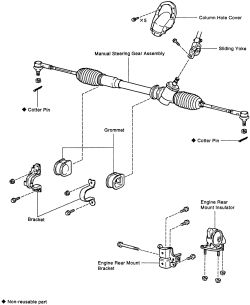
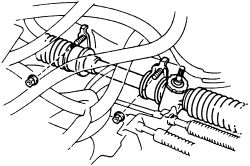
See Figure 1
If vehicle is equipped with an air bag system, after repair is complete remove the steering wheel and make sure that the spiral cable is aligned properly. Refer to the necessary service procedures in this section.
 |  |
Fig. Fig. 1: Exploded view of the 2WD manual steering gear assembly
- Disconnect the negative battery cable. Remove the upper and lower steering column covers.
CAUTION
On models with an airbag, wait at least 90 seconds from the time that the ignition switch is turned to the LOCK position and the battery is disconnected before performing any further work.
- Disconnect universal joint from the gear housing. Place matchmarks before removing set bolts.
- Raise and safely support the vehicle.
- Remove both front wheels.
- Remove the cotter pins from both tie rod joints and remove the nuts.
- Using a tie rod separator, remove both tie rod joints from the steering knuckles.
- Support the engine assembly and remove the engine mounting, lower the engine if necessary.
- Remove the nuts and bolts attaching the steering rack to the body.
- Remove any other necessary component to gain working access (if possible slide assembly out the wheel well opening) to remove the rack and pinion assembly from the vehicle. Remove the rack assembly.
- Install the rack assembly. Secure it with the retaining bolts and nuts and tighten them EVENLY to 43 ft. lbs. (58 Nm).
- Connect the tie rods to each steering knuckle. Tighten the nuts to 36 ft. lbs. (48 Nm) and install NEW cotter pins. Wrap the prongs of the cotter pin firmly around the flats of the nuts.
- Install the front wheels.
- Lower the car to the ground.
- Align matchmarks and connect universal joint to the steering gear housing. Tighten the upper and lower set bolts to 26 ft. lbs. (35 Nm).
- Install the steering column cover. Reconnect the negative battery cable. Check front wheel alignment.
See Figures 2 through 6
- Disconnect the negative battery cable. Remove the steering column cover.
CAUTION
On models with an airbag, wait at least 90 seconds from the time that the ignition switch is turned to the LOCK position and the battery is disconnected before performing any further work.
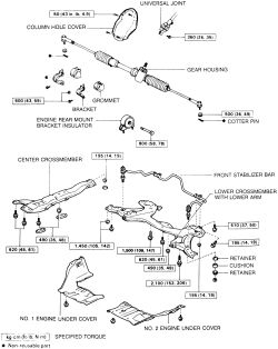
| |
Fig. Fig. 2: Exploded view of the 4WD manual steering gear assembly
- Raise and safely support the vehicle.
- Remove the cotter pins from both tie rod ends and remove the nuts.
- Using a tie rod separator, remove both tie rod ends from the steering knuckles.
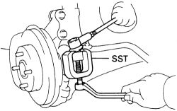
| |
Fig. Fig. 3: Using a tie rod puller, separate the ends from the steering knuckle arms
- Disconnect universal joint from the gear housing. Place matchmarks on the u-joint and control valve shaft. Loosen the upper side of the u-joint set bolt. Remove the lower side of the u-joint set bolt. Pull the u-joint upward from the control valve shaft.
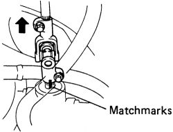
| |
Fig. Fig. 4: Place matchmarks on the u-joint and control valve shaft prior to removal
- Remove the gear housing set nuts.
| |
Fig. Fig. 5: Remove the manual gear housing set nuts-4WD models
- Remove both front wheels and engine undercovers.
- Attach an engine hoist chain to the engine hangers to support the engine.
CAUTION
The engine hoist is in place and under tension. Use care when repositioning the vehicle and make necessary adjustments to the engine support.
- Remove the bolts retaining the lower crossmember to the radiator support.
- Remove the covers from the front and center mount bolts.
- Remove the front mount bolts, then the center mount bolts.
- Support the crossmember (disconnect the stabilizer bar as necessary) and remove the rear mount bolts.
- Remove the bolts holding the center crossmember to the main crossmember.
- Use a floor jack and a wide piece of wood to support the main crossmember.
- Remove the bolts holding the main crossmember to the body.
- Remove the bolts holding the lower control arm brackets to the body.
- Slowly lower the main crossmember while holding onto the center crossmember.
- Lower the engine assembly if necessary, remove the nuts and bolts attaching the steering rack to the body.
- Pull the steering rack out from the side of the axle.
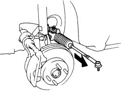
| |
Fig. Fig. 6: Pull the manual steering rack out from the vehicle through the side of the axle in this direction
- Place the steering rack in position and tighten the bracket bolts EVENLY to 43 ft. lbs. (58 Nm).
- Attach the tie rods to the knuckles. Tighten the nuts to 36 ft. lbs. (48 Nm) and install NEW cotter pins. Wrap the prongs of the cotter pin firmly around the flats of the nut.
- Position the center crossmember over the center and rear transaxle mount studs; start nuts on the center mount.
- Loosely install the bolts retaining the center crossmember to the radiator support.
- Loosely install the front mount bolts.
- Raise the main crossmember into position over the rear mount studs and align all underbody bolts. Install the rear mount nuts loosely.
- Install the main crossmember to underbody bolts loosely.
- Install the lower control arm bracket bolts loosely.
- Loosely install the bolts holding the center crossmember to the main crossmember.
- The crossmembers, bolts and brackets should now all be in place and held loosely by their nuts and bolts. If any repositioning is necessary, do so now.
-
Tighten the components below in the order listed to the correct torque specification:
Main crossmember to underbody bolts-152 ft. lbs. (206 Nm).Lower control arm bolts-105 ft. lbs. (142 Nm)Center crossmember to radiator support bolts-45 ft. lbs. (61 Nm)Front, center and rear mount bolts-58 ft. lbs. (78 Nm)
- Reconnect the stabilizer bar as necessary. Install the covers on the front and center mount bolts.
- Install the front wheels and engine undercovers.
- Lower the vehicle to the ground.
- Align matchmarks and connect universal joint to the steering gear housing. Tighten the upper and lower set bolts to 26 ft. lbs. (35 Nm).
- Install the steering column cover. Reconnect the negative battery cable. Check front wheel alignment.