
REMOVAL & INSTALLATION 2WD Models
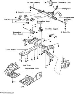
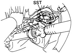
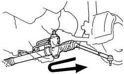
See Figures 1, 2 and 3
If vehicle is equipped with an air bag system, after repair is complete remove the steering wheel and make sure that the spiral cable is aligned properly. Refer to the necessary service procedures in this section.
 |  |
Fig. Fig. 1: Exploded view of the common 2WD power steering gear assembly
- Place the front wheels in the straight ahead position.
- Disconnect the negative battery cable. Remove the steering wheel pad and wheel. Refer to Steering Wheel Removal and Installation in this section.
- Raise and safely support the vehicle. If necessary, remove both front wheels.
- Remove the 2 engine under covers.
- Remove the cotter pins and nuts from both tie rod joints. Separate the joints from the knuckle using a tie rod joint separator.
- Remove the column hole cover retaining bolts, then pull the cover off.
- On some models it may be necessary to remove the left and right lower control arms.
- Disconnect universal joint from the gear housing. Place matchmarks before removing set bolts.
- Place a drain pan below the power steering rack assembly. Clean the area around the line fittings on the rack.
- Support the transaxle with a jack.
- Remove the engine crossmember. Remove the front pipe support.
- Remove the rear engine mount and bracket.
- Label and disconnect the fluid pressure and return lines at the steering rack.
- Remove the bolts and nuts holding the rack brackets to the body. It will be necessary to slightly raise and lower the rear of the transaxle to gain access to the bolts.
| |
Fig. Fig. 2: Disconnect the pressure feed hoses to the power steering gear assembly
- Remove the steering rack through the access hole. Slide the gear assembly to the right, then slide the assembly to the left and pull it out.
| |
Fig. Fig. 3: Pull the power steering rack out from the vehicle through the side of the axle in this direction
- Place the steering rack in position through the access hole and install the retaining brackets to the body. Tighten the nuts and bolts EVENLY to 43 ft. lbs. (78 Nm).
- Connect the fluid lines (always start the threads by hand before using a tool) to the steering rack.
- Install the nut and bolt holding the rear engine mount to the mount bracket.
- Reinstall the engine crossmember bolts and tighten.
- Remove the jack from the transaxle.
- Connect the tie rod ends to the knuckles. Tighten the nuts to 36 ft. lbs. (48 Nm) and install NEW cotter pins. Wrap the prongs of the cotter pin firmly around the flats of the nut.
- Install the wheels and lower the vehicle to the ground.
- Align matchmarks and connect universal joint to the steering gear housing. Tighten the upper and lower set bolts to 26 ft. lbs. (35 Nm).
- Install the steering column cover. Add fluid and bleed the system.
- Reconnect the negative battery cable. Check front wheel alignment.
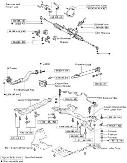
See Figure 4
- Disconnect the negative battery cable. Remove the steering column cover.
- Disconnect universal joint from the gear housing. Place matchmarks before removing set bolts.
- Raise and safely support the vehicle.
| |
Fig. Fig. 4: Exploded view of the common 2WD power steering gear assembly
- Remove both front wheels and engine undercovers.
- Install an engine support and tension it to support the engine without raising it.
CAUTION
The engine hoist is now in place and under tension. Use care when repositioning the vehicle and make necessary adjustments to the engine support.
- Disconnect and (position out of the way) front exhaust pipe. Matchmark and remove the propeller shaft assembly. Disconnect the front stabilizer bar.
- Remove the bolts holding the center crossmember to the radiator support. Remove the covers from the front and center mount bolts.
- Remove the front mount bolts, then the center mount bolts and then the rear mount bolts.
- Remove the bolts holding the center crossmember to the main crossmember.
- Use a floor jack and a wide piece of wood to support the main crossmember.
- Remove the bolts holding the main crossmember to the body.
- Remove the bolts holding the lower control arm brackets to the body.
- Slowly lower the main crossmember while holding onto the center crossmember.
- Remove the cotter pins from both tie rod ball joints and remove the nuts.
- Using a tie rod separator, remove both tie rod joints from the knuckles.
- Label and disconnect the fluid pressure and return lines from the rack.
- Remove the nuts and bolts attaching the steering rack to the body.
- Remove the steering rack.
- Place the steering rack in position and tighten the bracket bolts EVENLY to 43 ft. lbs. (58 Nm).
- Connect the fluid lines to the steering rack. Make certain the fittings are correctly threaded before tightening them.
- Attach the tie rods to the knuckles. Tighten the nuts to 36 ft. lbs. (48 Nm) and install NEW cotter pins. Wrap the prongs of the cotter pin firmly around the flats of the nut.
- Position the center crossmember over the center and rear transaxle mount studs; start nuts on the center mount.
- Loosely install the bolts holding the center crossmember to the radiator support.
- Loosely install the front mount bolts.
- Raise the main crossmember into position over the rear mount studs and align all underbody bolts. Install the rear mount nuts loosely.
- Install the main crossmember to underbody bolts loosely.
- Install the lower control arm bracket bolts loosely.
- Loosely install the bolts holding the center crossmember to the main crossmember.
- The crossmembers, bolts and brackets should now all be in place and held loosely by their nuts and bolts. If any repositioning is necessary, do so now.
-
Tighten the components below in the order listed to the correct torque specification:
Main crossmember to underbody bolts-152 ft. lbs. (206 Nm).Lower control arm bolts-105 ft. lbs. (142 Nm).Center crossmember to radiator support bolts-45 ft. lbs. (61 Nm).Front, center and rear mount bolts-45 ft. lbs. (61 Nm).
- Install the covers on the front and center mount bolts. Install the propeller (align matchmarks) shaft assembly. Reconnect front exhaust pipe. Connect the front stabilizer bar.
- Install the front wheels and engine undercovers.
- Lower the vehicle to the ground. Align matchmarks and connect universal joint to the steering gear housing. Tighten the upper and lower set bolts to 26 ft. lbs.
- Install the steering column cover. Add fluid and bleed the system.
- Reconnect the negative battery cable. Check front wheel alignment.