
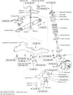
REMOVAL & INSTALLATION 1988-92 ModelsEXCEPT AUTOMATIC LEFT SIDE
See Figure 1 through 6
- Remove the front wheel. Place a floor jack under the suspension crossmember. Use a broad piece of wood between the jack and crossmember to evenly distribute the loading.
 |  |
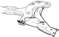
Fig. Fig. 1: Front suspension components-1988-92 models
- On 4A-GE engines, remove the stabilizer link.
- On all other models, remove the stabilizer bar nut holding the bar to the lower control arm and separate the unit form the vehicle.
| |
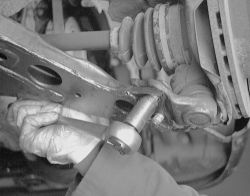
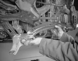
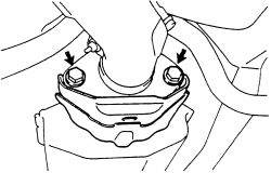
Fig. Fig. 2: Remove the two nuts retaining the control arm to the ball joint
- Loosen the lower control arm front bolt.
| |
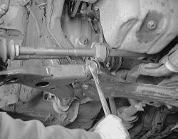
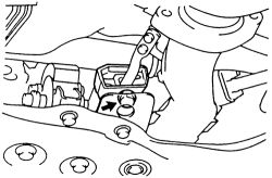
Fig. Fig. 3: Now remove the bolts retaining the control arm to the engine crossmember
- Remove the rear bracket bolts and nuts. Remove the rear bracket and stabilizer bar bracket. Remove the lower arm front bolt and lower the control arm from the vehicle.
| |
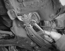
Fig. Fig. 4: Remove the bolts and nut holding the bracket to the frame
| |
Fig. Fig. 5: Pull the arm out from under the vehicle
| |
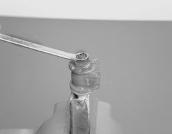
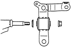
Fig. Fig. 6: When replacing the bushing, remove the nut first
- Install the lower control arm to the body.
- Move the stabilizer bar into position.
- Temporiarily install and tighten the lower control arm front bolt.
- Install the stabilizer bar bracket and rear bracket, then temporarily tighten the bolts and nut.
- Install and tighten the bolt and two nuts to 105 ft. lbs. (142 Nm).
- Connect the stabilizer bar to the lower control arm with the bolt and nut. If needed, connect the other side also. Tighten to 13 ft. lbs. (18 Nm).
-
Remove the stands and bounce the vehicle up and down to stabilize the suspension. Tighten the lower arm bolt, rear bracket bolts and nut.
Lower arm front bolt-174 ft. lbs. (235 Nm)Rear bracket lower arm side-94 ft. lbs. (127 Nm)Rear bracket stabilizer bar side-37 ft. lbs. (50 Nm)Rear bracket bolt and nut-14 ft. lbs. (19 Nm)
- Check the front end wheel alignment.
See Figures 7, 8 and 9
- Remove the front wheel. Place a floor jack under the suspension crossmember. Use a broad piece of wood between the jack and crossmember to evenly distribute the loading.
- Disconnect the left and right lower control arms from the steering knuckles.
- Remove the left and right stabilizer bar nuts holding the bar to the lower control arms and disconnect the stabilizer bar.
- Remove the left and right lower arm rear brackets.
- Move the stabilizer bar toward the rear side, then remove the stabilizer bar bracket.
- Remove the six bolts and two nuts, then remove the suspension crossmemeber with lower control arms.
| |
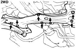
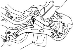
Fig. Fig. 7: Remove the bolts and nuts retaining the crossmember and lower control arms-2WD models
| |
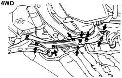
Fig. Fig. 8: Remove the bolts and nuts retaining the crossmember and lower control arms-4WD models
- Remove the lower control arm from the crossmember. Inspect and replace any bushing necessary.
| |
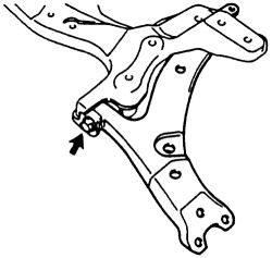
Fig. Fig. 9: Remove the remaining bolt retaining the lower control arm to the crossmember
- Temporarily install the lower control arm to the crossmemeber with a bolt.
- Install the suspension crossmember with the lower control arm to the body.
- Move the stabilizer bar in position and temporarily install the stabilizer bar bracket and rear bracket.
- Install the left and right lower control arm to each steering knuckle, then tighten the bolts and nuts to 105 ft. lbs. (142 Nm).
- Connect the stabilizer bar to the lower control arm with the bolt and nut. If needed, connect the other side also. Tighten to 13 ft. lbs. (18 Nm).
-
Remove the stands and bounce the vehicle up and down to stabilize the suspension. Tighten the lower arm bolt, rear bracket bolts and nut.
Lower arm front bolt-174 ft. lbs. (235 Nm)Rear bracket lower arm side-94 ft. lbs. (127 Nm)Rear bracket stabilizer bar side-37 ft. lbs. (50 Nm)Rear bracket bolt and nut-14 ft. lbs. (19 Nm)
- Check the front end wheel alignment.
See Figures 10, 11 and 12
- Remove the front wheel. Place a floor jack under the suspension crossmember. Use a broad piece of wood between the jack and crossmember to evenly distribute the loading.
| |
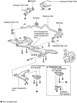
Fig. Fig. 10: Exploded view of the lower control arm components
- On models with a stabilizer bar, disconnect the bar link from the lower control arm.
- Remove the ball joint form the lower control arm.
- Remove the nut, 3 bolts and stabilizer bar bracket with bar.
| |
Fig. Fig. 11: Remove the bolt retaining the lower control arm to the body
- Remove the bolt and lower control arm.
- Install the lower control arm to the body.
- Move the stabilizer bar into position.
- Temporarily install and tighten the lower control arm front bolt.
- Install the stabilizer bar bracket and rear bracket, then temporarily tighten the bolts and nut.
- Connect the stabilizer bar to the lower control arm with the bolt and nut. If needed, connect the other side also.
- Install the wheel.
-
Remove the stands and bounce the vehicle up and down to stabilize the suspension. Tighten the lower arm bolt, rear bracket bolts and nut.
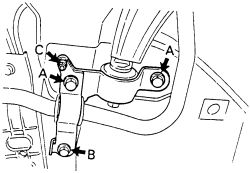
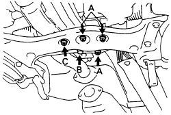
Bolt A-108 ft. lbs. (147 Nm)Bolt B-37 ft. lbs. (50 Nm)Nut C-14 ft. lbs. (19 Nm)
| |
Fig. Fig. 12: Tightening sequence on the control arm bracket bolts-1993-95 models
- Check the front end wheel alignment.
See Figures 13 through 18
- Remove the front wheel. Place a floor jack under the suspension crossmember. Use a broad piece of wood between the jack and crossmember to evenly distribute the loading.
- On models with a stabilizer bar, disconnect the bar link from the lower control arm.
- Remove the ball joint form the lower control arm.
- Remove the nut, 3 bolts and stabilizer bar bracket with bar.
- Disconnect the front pipe from the center pipe and discard the gasket.
| |
Fig. Fig. 13: Separate the exhaust where the front pipe meets the center pipe
- On the stabilizer bar, remove the nut obtained through a hole in the crossmember. Lower the stabilizer bar. Remove the grommet, 4 nuts and bolt.
| |
Fig. Fig. 14: Remove the bolt for the stabilizer bar through the crossmember
- Support the suspension crossmember with a jack.
- Remove the 6 bolts and suspension crossmemeber with the control arms attached. Remove the bolt retaining the control arm to the crossmember.
| |
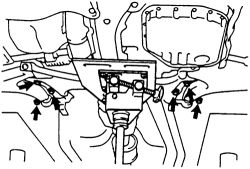
Fig. Fig. 15: With the suspension supported, remove these six crossmember bolts-1993-95 automatic left side
- Remove the nut, control arm bracket and cushion retainer.
| |
Fig. Fig. 16: Remove the bolt retaining the lower control arm to the crossmember
| |
Fig. Fig. 17: The washer, bracket and nut are removed and installed in this order
- Attach the lower control arm retainer and tighten the nut hand tight for now.
- Attach the lower control arm to the crossmember.
- Place the crossmember with control arms into the vehicle, tighten the retaining bolts to 152 ft. lbs. (206 Nm).
-
Install the 4 nuts and bolt, tighten to the following:
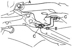
Nut A-35 ft. lbs. (48 Nm)Bolt B-45 ft. lbs. (61 Nm)Nut C-45 ft. lbs. (61 Nm)Control arm bracket retainer nut-101 ft. lbs. (137 Nm)
| |
Fig. Fig. 18: Center bolt and nuts crossmember tightening locations-1993-95 automatic left side
- Attach the stabilizer bar, install the nut and tighten to 14 ft. lbs. (19 Nm).
- Place a new gasket into position and attach the front pipe to the center pipe. Tighten the retaining nuts to 32 ft. lbs. (43 Nm).
- Install the remaining components in the reverse order.
-
Remove the stands and bounce the vehicle up and down to stabilize the suspension. Tighten the lower arm bolt, rear bracket bolts and nut.
Bolt A-108 ft. lbs. (147 Nm)Bolt B-37 ft. lbs. (50 Nm)Nut C-14 ft. lbs. (19 Nm)
- Check the front end wheel alignment.
See Figures 19 and 20
- Remove the front wheel. Place a floor jack under the suspension crossmember. Use a broad piece of wood between the jack and crossmember to evenly distribute the loading.
- Remove the stabilizer bar on vehicles equipped.
- Remove the bolt and 2 nuts retaining the ball joint to the lower control arm.
- When working on manual transaxles and right side automatics, remove the 4 bolts and lower control arm.
- If working on the left side on automatics, remove the 10 bolts, 4 nuts and crossmember with the lower control arms attached. Remove the lower control arm from the crossmember once removed from the vehicle.
-
To install the left side automatics, attach the lower control arm to the crossmember and place the assembly into the vehicle. Support the crossmember securely.
- Install all of the crossmember retaining bolts. Do not tighten them at this tome. Lower the vehicle and stabilize the suspension by bouncing it up and down a few times. Raise and support the vehicle.
-
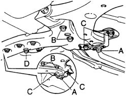
Once the suspension is stabilized, tighten the lower control arm bolt to 161 ft. lbs. (218 Nm) and tighten the crossmember bolts A, B and C.
Bolt A-129 ft. lbs. (175 Nm)Bolt B-167 ft. lbs. (225 Nm)Bolt C-109 ft. lbs. (147 Nm)Bolt D-45 ft. lbs. (60 Nm)Nut-45 ft. lbs. (60 Nm)
- tighten the remaining bolts and nuts.
| |
Fig. Fig. 19: Tightening identification for the control arm bracket bolts-1996-97 models
| |
Fig. Fig. 20: Tightening bolt identification for the crossmember bolts-1996-97 models
- Install the ball joint and tighten to 105 ft. lbs. (142 Nm).
- Install the stabilizer bar and front wheel.
- Check the front end wheel alignment.
CONTROL ARM BUSING REPLACEMENT
If lower control arm bushings are worn or damaged, replace the complete assembly.