
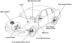
See Figure 1
The system is designed to prevent wheel lock-up during hard or emergency braking. By preventing wheel lock-up, maximum braking effort is maintained while preventing loss of directional control. Additionally, some steering capability is maintained during the stop. The ABS system will operate regardless of road surface conditions.
 |  |
Fig. Fig. 1: Anti-Lock Brake System (ABS) component locations
There are conditions for which the ABS system provides no benefit. Hydroplaning is possible when the tires ride on a film of water, losing contact with the paved surface. This renders the vehicle totally uncontrollable until road contact is regained. Extreme steering maneuvers at high speed or cornering beyond the limits of tire adhesion can result in skidding which is independent of vehicle braking. For this reason, the system is named anti-lock rather than anti-skid.
Under normal braking conditions, the ABS system functions in the same manner as a standard brake system. The system is a combination of electrical and hydraulic components, working together to control the flow of brake fluid to the wheels when necessary.
The Anti-lock Brake System Computer (ABSC) is the electronic brain of the system, receiving and interpreting speed signals from the speed sensors. The ABSC will enter anti-lock mode when it senses impending wheel lock at any wheel and immediately controls the brake line pressure(s) to the affected wheel(s). The actuator assembly is separate from the master cylinder and booster. It contains the wheel circuit valves used to control the brake fluid pressure to each wheel circuit.
During anti-lock braking, line pressures are controlled or modulated by the rapid cycling of electronic valves within the actuator. These valves can allow pressures within the system to increase, remain constant or decrease depending on the needs of the moment as registered by the ABSC.
The operator may hear a popping or clicking sound as the pump and/or control valves cycle on and off during normal operation. The sounds are due to normal operation and are not indicative of a system problem. Under most conditions, the sounds are only faintly audible. If ABS is engaged, the operator may notice some pulsation in the body of the vehicle during a hard stop; this is generally due to suspension shudder as the brake pressures are altered rapidly and the forces transfer to the vehicle.
Although the ABS system prevents wheel lock-up under hard braking, as brake pressure increases, wheel slip is allowed to increase as well. This slip will result in some tire chirp during ABS operation. The sound should not be interpreted as lock-up but rather than as indication of the system holding the wheel(s) just outside the point of lock-up. Additionally, the final few feet of an ABS-engaged stop may be completed with the wheels locked; the system does not operate below 4 mph.
SYSTEM COMPONENTS Wheel Speed Sensors
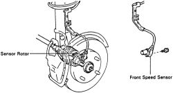
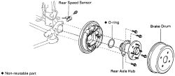
See Figures 2 and 3
The speed of each wheel is monitored by a sensor. A toothed wheel (sensor rotor) rotates in front of the sensor, generating a small AC voltage which is transmitted to the ABS controller. The ABS computer compares the signals and reacts to rapid loss of wheel speed at a particular wheel by engaging the ABS system. Each speed sensor is individually removable. In most cases, the toothed wheels may be replaced if damaged, but disassembly of other components such as hub and knuckle, constant velocity joints or axles may be required.
| |
Fig. Fig. 2: Exploded view of the front wheel speed sensors
| |
Fig. Fig. 3: Exploded view of the rear wheel speed sensors
This computer-based unit interprets inputs from the speed sensors, the brake lights and the brake warning lamp circuit. After processing the inputs, the unit controls output electrical signals to the hydraulic control solenoids, causing them to increase, decrease or hold brake line pressures. Additionally, the controller oversees operation of the pump motor and the ABS warning lamp.
Additionally, the controller constantly monitors system signals, performs a system actuation test immediately after engine start-up and can assign and store diagnostic fault codes if any errors are noted.
ABS ActuatorAlso called the hydraulic unit, the actuator contains the control solenoids for each brake circuit. The pump which maintains the system pressure during ABS braking is also within this unit. The control relay is mounted externally near the actuator. The ABS actuator can only be replaced as a unit; with the exception of the relay, individual components cannot be replaced.
ABS Warning LampThe ABS dashboard warning lamp is controlled by the ABS controller. The lamp will illuminate briefly when the ignition switch is turned ON as a bulb check. The lamp should then extinguish and remain out during vehicle operation. If only the ABS warning lamp illuminates while driving, the controller has noted a fault within the ABS system. ABS function is halted, but normal braking is maintained.