
SYSTEM PRECAUTIONS
DEPRESSURIZING THE SYSTEM
The system operates on low hydraulic pressure and requires no special system depressurization prior to the opening of hydraulic lines or other system repairs. Simply verify the ignition switch is OFF and pump/motor is not running.
DIAGNOSTIC CODES
If a malfunction occurs, the system will identify the problem and the computer will assign and store a fault code for the fault(s). The dashboard warning lamp will be illuminated to inform the driver that a fault has been found.
During diagnostics, the system will transmit the stored code(s) by flashing the dashboard warning lamp. If two or more codes are stored, they will be displayed from lowest number to highest, regardless of the order of occurrence. The system does not display the diagnostic codes while the vehicle is running.
INITIAL CHECKS Visual Inspection
Before diagnosing an apparent ABS problem, make absolutely certain that the normal braking system is in correct working order. Many common brake problems (dragging parking brake, seepage, etc.) will affect the ABS system. A visual check of specific system components may reveal problems creating an apparent ABS malfunction. Performing this inspection may reveal a simple failure, thus eliminating extended diagnostic time.
Also check battery condition; approximately 12 volts is required to operate the system. Turn the ignition switch ON and check that the dashboard warning lamp (ABS) comes on for 3-4 seconds. If the lamp does not come on, repair the fuse, bulb or wiring.
- Inspect the tire pressures; they must be approximately equal for the system to operate correctly.
- Inspect the brake fluid level in the reservoir.
- Inspect brake lines, hoses, master cylinder assembly, brake calipers and cylinders for leakage.
- Visually check brake lines and hoses for excessive wear, heat damage, punctures, contact with other parts, missing clips or holders, blockage or crimped.
- Check the calipers or wheel cylinders for rust or corrosion. Check for proper sliding action if applicable.
- Check the caliper and wheel cylinder pistons for freedom of motion during application and release.
- Inspect the wheel speed sensors for proper mounting and connections.
- Inspect the sensor wheels for broken teeth or poor mounting.
- Inspect the wheels and tires on the vehicle. They must be of the same size and type to generate accurate speed signals.
- Confirm the fault occurrence with the operator. Certain driver induced faults, such as not releasing the parking brake fully, will set a fault code and trigger the dash warning light(s). Excessive wheel spin on low-traction surfaces, high speed acceleration or riding the brake pedal may also set fault codes and trigger a warning lamp. These induced faults are not system failures but examples of vehicle performance outside the parameters of the control unit.
- Many system shut-downs are due to loss of sensor signals to or from the controller. The most common cause is not a failed sensor but a loose, corroded or dirty connector. Incorrect adjustment of the wheel speed sensor will cause a loss of wheel speed signal. Check harness and component connectors carefully.
READING CODES
Turn the ignition ON, use a jumper wire to connect terminals Tc and E1 of the check connector or DLC1. Remove the short pin from the terminals of the DLC1.
If a fault code has been set, the dashboard warning lamp will begin to blink 4 seconds later. The number of flashes corresponds to the first digit of a 2-digit code; after a 1.5 second pause, the second digit is transmitted. If a second code is stored, it will be displayed after a 2.5 second pause. Once all codes have been displayed, the entire series will repeat after a 4 second pause. If no codes have been stored, the warning lamp will flash continuously every 1/2 second with no variation.
CLEARING DIAGNOSTIC CODES
See Figures 1 and 2
With the system set to read codes (short pin disconnected and jumper wire in place), turn the ignition switch ON. Apply the brake pedal 8 or more times within 3 seconds.
After the rapid pedal application, the dash warning lamp should display constant flashing, indicating a normal system. If codes are still displayed, make certain the repairs made to the system are correct. Also inspect the brake light switch at the brake pedal for any binding or sticking.
Once the codes are cleared, disconnect the jumper wire. Reinstall the short pin. The dash warning lamp should go out.
 |  |
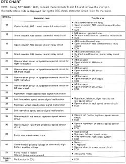
Fig. Fig. 1: DTC Chart
| |
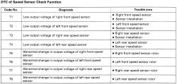
Fig. Fig. 2: DTC of Speed Sensor Check Function